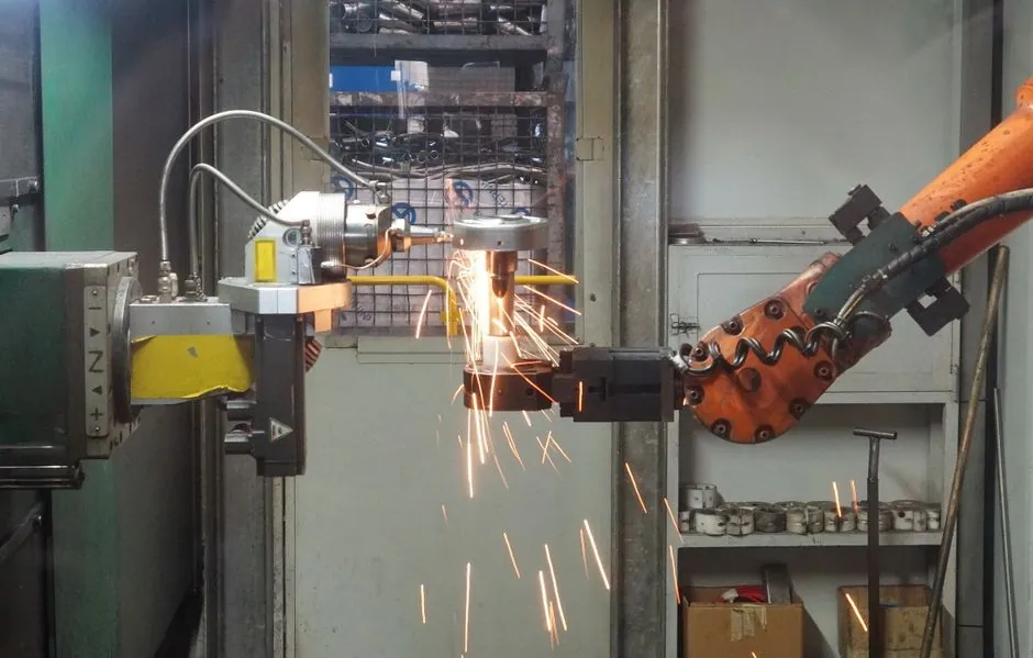
A thin-wall electronics housing should be routed to a cold-chamber machine for larger aluminum parts, or a hot-chamber machine for compact zinc parts with fine details and integrated shielding features [S2][S3].
Machine selection is a die-fill and production problem, not a tonnage-only decision: flow length, wall-thickness uniformity, projected area, shot weight, tooling size, vacuum, venting and annual output all affect the correct configuration [S1].
Choose the alloy and machine route by housing geometry
Cold-chamber die casting is used for aluminum, while hot-chamber machines are used for low-melting-temperature alloys such as zinc.
For electronics housings, cold-chamber aluminum equipment is the stronger candidate when the enclosure is large, light, thermally loaded or intended for outdoor use [S2]. Hot-chamber zinc equipment becomes credible when the part is compact, dimensionally tight, detailed, and intended as a shield, connector body, plug housing or miniature electronics frame [S2].
The same physical enclosure can therefore lead to different equipment choices. A large heat-spreading chassis and a miniature board shield may both be called electronics housings, but they have different melting-point, flow, tolerance and tooling requirements [S2].
Do not select a universal thin-wall thickness
Aluminum wall feasibility has no single universal minimum because fill distance, part size, alloy, rib layout, gate location, venting, vacuum assistance, mold temperature and inspection requirements interact [S1]. A short-flow miniature frame may accept a thinner section than a large housing with long ribs and broad panels, while the last thin section reached by the metal may behave differently from a section beside the gate [S1].
The RFQ should therefore include the CAD model, a wall-thickness map, alloy preference, annual quantity, critical surfaces and the functional reason for the wall thickness [S1]. The tool review should identify the farthest thin sections from the gate rather than specifying one nominal wall value for the entire casting [S1].
Local features also need explicit treatment. Ribs and bosses can add stiffness without thickening the whole shell, but they can also produce localized shrinkage, flow hesitation or ejector-mark conflicts [S1]. Machined datums, holes and sealing faces need stock allowance because drilling into an already thin wall can leave insufficient material [S1].
Size the machine from the complete die and casting load
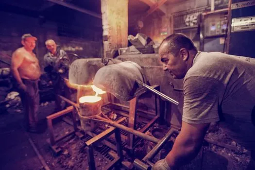
The industrial label does not determine machine capacity; alloy, geometry, projected area, shot weight, die dimensions, finish, volume and automation must all be defined before model selection [S2]. Machine selection should account for the alloy, geometry, projected area, shot, die, performance, finish, volume, and product validation.
For a die-casting machine shortlist, evaluate the alloy, geometry, projected area, shot, die, performance, finish, volume, and product-validation requirements. Size the machine around the casting, die, shielding and thermal interfaces, sealing boundary, finish, output, automation, and acceptance plan.
Thin-wall feasibility depends on factors such as alloy grade, flow length, part size, rib layout, gate location, venting, vacuum assistance, thermal balance, surface requirement, and inspection criteria. The shot sleeve and cold-chamber injection system also require a documented alloy-compatible configuration.
Compare aluminum and zinc by more than material cost
Zinc is selected when compact geometry, fine detail and high dimensional repeatability justify its higher material density [S2][S4].
These are orientation- and feature-specific design guidelines, not guaranteed part tolerances. The supplier must apply its own tolerance grade, critical-feature limits and acceptance plan to the actual drawing.
The comparison is direct: aluminum wins for large, lightweight and thermally demanding housings; zinc wins for compact precision hardware; Vacuum assistance is one of the factors affecting thin-wall feasibility.; This decision also matches the comparison between die cast and CNC-machined telecom enclosures.
Validate shielding, thermal and sealing interfaces
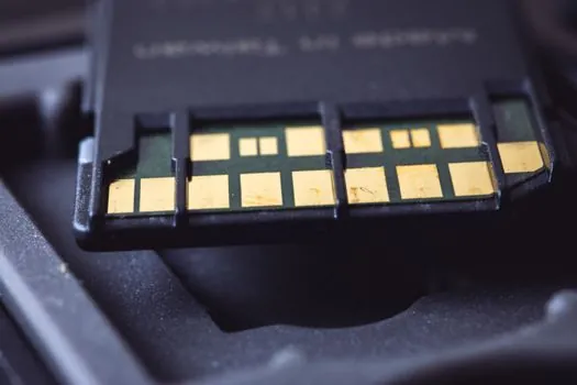
An electronics housing requires control of six interfaces: shielding seams and apertures, heat transfer from source to ambient, the complete seal, grounding and bonding, connector fit, and mechanical assembly [S2]. For electrical and electronic housings, evaluate shielding seams and apertures, the thermal path from source to ambient, the complete assembly seal, and fit and bonding.
Use wall-thickness changes, ribs and bosses to create stiffness while marking all load-bearing, grounded and sealing interfaces on the drawing [S1]. The casting review should identify critical ribs, screw bosses and assembly loads because those features often control local wall thickness and ejector placement [S1].
The acceptance plan should separate as-cast, machined and finished conditions. It should define dimensions, cosmetic surfaces, flash and parting-line limits, porosity acceptance, leak testing, grounding continuity, heat-transfer performance and electromagnetic-emissions requirements. A metal box is not a validated enclosure until those interfaces are tested as an assembly [S2].
Match the die construction to volume and change risk
Thin, rigid walls are a recognized die-casting advantage because they can reduce package size while forming complex geometry at production rates that differ from machining [S5]. The tooling must provide premium tool steel, controlled cooling, adequate ejector support, vent and overflow capacity, and a gate arrangement that balances flow through the last thin sections [S1][S5].
Tool construction should address the parting line, moving core slides, die life, porosity, heat transfer and post-cast machining [S5]. Multi-slide tooling is particularly relevant to connector bodies, shield shells and precision hardware where undercuts or separated shielding partitions are required [S2].
Do not choose a production machine for a low-volume program unless the supplier confirms that shot capacity, platen dimensions, oil routing, automation and control assumptions remain sensible. Conversely, do not buy a small bench machine for a high-volume program without confirming cold-chamber performance, die temperature control, shot repeatability, machine availability and planned preventive maintenance.
Use a staged selection and acceptance process
Shortlist one cold-chamber aluminum platform and one hot-chamber zinc platform only when both routes are technically credible, then compare them against four criteria: part size and weight, thin-wall fill risk, dimensional and shielding requirements, and annual output [S2]. Select the route before finalizing machine tonnage and model.
The next trackable action is a manufacturability review with the CAD file, thickness map, material grade, annual quantity, critical surfaces and machining allowance. That review should produce a proposed alloy, gate and vent strategy, trial-part plan, dimensional capability, cycle-time estimate and inspection criteria before a production machine is accepted [S1][S2].
Reject any proposal that relies on a single generic wall-thickness figure, omits the farthest fill point, or treats shielding, thermal performance and sealing as properties of the metal alone. A defensible selection links the specific housing geometry to the machine, die, process controls and measurable acceptance plan.