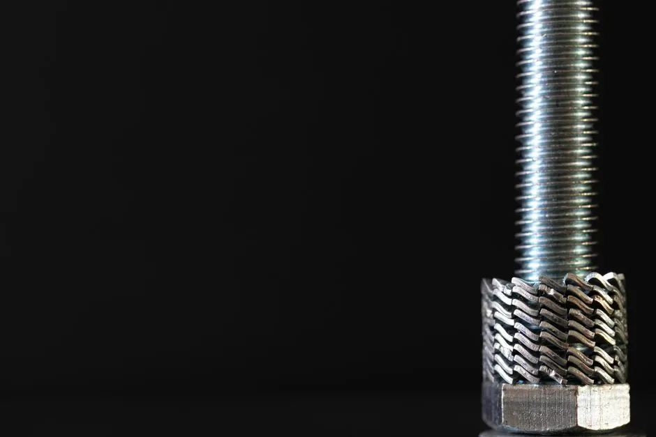
Milled steel fiber with a rough, twisted surface reaches a bond strength in cementitious mortar comparable to crimped steel fiber and markedly higher than standard hooked-end fiber of the same geometry, according to pullout data from Ding et al. [S2]. The mechanism is a three-part stack: chemical adhesion at the interfacial transition zone, frictional shear along the milled surface roughness, and mechanical anchorage from the deformed end hook. The roughness and the end hook are not redundant; they operate in sequence, and removing either one drops the measured peak pullout load.
For a steel fiber to perform as designed, the matrix has to fail in a controlled way during pullout, not in a brittle snap. Milled, twisted surface fiber is therefore specified for SFRC where the matrix is medium-strength (cubic compressive strength in the 40-90 MPa window) and where the design wants the fiber to slide, scrape, and absorb energy rather than rupture [S2]. The geometry of the milled deformation, not just the rough surface itself, sets the working envelope of the bond.
Three-component bond stack: adhesion, friction, mechanical anchorage
Deformed concrete fiber bond breaks into three load-transfer terms acting at the fiber-matrix interface: chemical adhesion across the interfacial transition zone (active in the initial millimetres of slip), physical friction set by the surface roughness of the fiber, and mechanical anchorage from the deformed geometry [S2]. For milled twisted fiber, the friction term is non-trivial because the milling process leaves a surface texture that interlocks with the cement paste, not just a smooth sliding contact.
The three terms do not activate simultaneously. Adhesion dominates in the first 0.1-0.3 mm of slip, friction takes over as the bond cracks and slips along the rough interface, and mechanical anchorage engages last, governed by the end-hook geometry and the matrix's resistance to crushing at the hook root [S2]. Single-fiber pullout tests on manufactured-sand mortar show that the characteristic pullout load-slip curve (PL-S) for deformed steel fiber resolves into a debonding branch, a peak branch, and a residual branch, and the relative size of these branches is set by which mechanism is doing the work [S1].
The Naaman and Najim framework from 1991 still underpins the way these curves are interpreted: derive a local bond shear stress versus slip from the global pullout load versus end-slip, and treat that local curve as the constitutive property of the interface [S5]. For milled fiber specifically, the friction term shows up as a long, slowly-decaying residual branch, because the rough surface keeps re-engaging as the fiber slides through the mortar channel.
How inclination angle and fiber spacing shift the bond mechanism
Inclination of the fiber relative to the pullout direction is the single biggest variable in real SFRC, because the fibers are randomly distributed in three dimensions, and the same pullout test on aligned versus inclined fiber gives different mechanisms entirely [S1]. In a 15-group pullout study on hook-end fiber in manufactured-sand mortar, inclination angles of 0°, 15°, 30°, 45°, and 60° were crossed with fiber spacings from 3.5 mm to 21.2 mm, and the bond was reported to be dominated by the resistance of mortar to peeling off near the pullout surface and by scraping along the pullout direction [S1].
When the inclination angle exceeds 15° to 30°, bond performance generally drops because the mortar on the transverse section peels off to a certain depth, and that peeled zone no longer contributes friction or anchorage [S1]. For fiber spacing above 5 mm, the worst-case bond performance is observed as the slip of the fiber scrapes mortar out of the channel along with the fiber, depleting the matrix locally. This matrix-scraping failure mode is the one a milled twisted fiber is actually well suited to, because its rough surface generates high frictional resistance against the surrounding matrix even as the matrix is being scoured away.
A practical rule: keep the design target such that the inclination of the dominant bridging fibers stays in the 0-15° range if bond strength is the priority, but allow inclination up to 30° if the priority is energy absorption and you have the matrix strength to absorb the peeling-off stress. Above 60°, fiber rupture becomes a real risk, and at that point the high tensile strength of the wire matters more than the surface treatment [S1].
Milled vs crimped vs hooked-end: a criteria comparison
Across the three common deformed geometries used in SFRC, the bond behavior differs in a way that is specification-relevant, not academic. Milled twisted fiber and crimped fiber reach similar bond strength in the same matrix, both notably above hooked-end fiber at the same length and diameter, with the end hook on the milled fiber adding a second anchoring stage on top of the rough-surface friction [S2]. Hooked-end fiber, by contrast, fails by the end hook being straightened without fiber breakage, which is a ductile, energy-absorbing failure mode, but with a lower peak load than the milled or crimped geometry.
The decision boundary between milled twisted and crimped is rarely bond strength alone. Milled twisted is easier to bundle and disperse with water-soluble glue because the rough surface helps the glue grip during the bundle stage and releases cleanly during mixing, and this is the route most modern glued fiber products take [S4][S6]. Crimped fiber, with its regular wave geometry, tends to cluster more during pumping and high-dosage mixes. For mixes above 40 kg/m³ of fiber, the dispersion advantage of milled fiber typically outweighs the small bond-strength difference.
Matrix strength matching: avoiding the under-utilisation trap
Bond performance is a two-sided contract between fiber and matrix, and mismatching either side wastes the system. High-strength steel fiber in a low-strength matrix pulls out with low anchorage effect and under-utilises the fiber's tensile capacity; low-strength steel fiber in a high-strength matrix breaks at the same embedment length instead of sliding, which is good for toughness but cuts the pullout work [S2].
Pullout data on hooked-end fiber with 2600 MPa tensile strength embedded in 84 MPa and 44 MPa concrete shows peak pullout loads nearly twice those of the same fiber at 1300 MPa tensile strength, but only in the high-strength matrix [S2]. In the 44 MPa matrix, the higher-strength fiber simply slips out before the matrix can mobilise the end-hook, and the bond strength difference between fiber grades collapses. Milled twisted fiber follows the same logic: the rough surface and the end hook both need matrix support to engage, and that support scales with the matrix's tensile and shear capacity at the hook root.
For typical 30-50 MPa commercial concrete, milled twisted fiber at 1100-1600 MPa tensile strength is the operating sweet spot. For 60-90 MPa high-performance concrete, the same geometry at 2000+ MPa tensile strength unlocks the full bond capacity. Going past that, in the ultra-high-performance concrete (UHPC) range above 120 MPa, the matrix is so dense that the chemical adhesion term alone carries a large fraction of the load, and the surface treatment's contribution shifts toward corrosion-driven bond modification, which is its own topic [S3].
Corrosion at the bond interface: chloride exposure, debonding, and pullout energy

Surface corrosion of steel fiber in the bonded region is not always a degradation: in UHPC pullout tests, up to 20 weeks of immersion in 3.5% NaCl raised bond strength by up to 54% and pullout energy by up to 90%, because the corrosion product (ferric oxide) roughens the fiber-matrix interface and roughly doubles the frictional shear stress at the interface [S3]. The same mechanism has a darker side, because the chemically debonded region of the fiber starts corroding within 4 weeks of immersion, while the bonded region with its densified microstructure stays largely intact [S3].
Twisted geometry makes the situation worse than straight geometry under corrosion, because the twisted surface traps chloride solution in the channels and the surface area exposed to the electrolyte is higher per unit embedded length [S3]. In a fully debonded fiber pulled out of UHPC after 20 weeks of immersion, premature fiber rupture was observed at the corroded section, which means the corrosion-driven bond-strength gain is paid for with a loss of ductility and a sharper post-peak drop in the load-slip curve. For service-life design, the trade is real: a modest chloride exposure can lift the peak load but shorten the ductile tail, and a structure that relies on the ductile tail for toughness (tunnel segments, impact-loaded slabs) cannot afford that trade.
For applications in marine or de-icing-salt environments, the practical move is to specify stainless or coated steel fiber, or to cap the dosage and accept a lower bond gain, rather than rely on corrosion as a bond-enhancement mechanism. Where corrosion-resistant grades are not an option, controlling the matrix cracking and limiting crack-mouth opening to under 0.5 mm keeps the bonded region dense enough to slow chloride ingress to the fiber surface [S3].
Specification and sourcing: what to write into the mix sheet
On a concrete mix sheet, the relevant variables for milled twisted steel fiber are: fiber length (typically 30-60 mm), diameter (0.5-1.0 mm), aspect ratio (length/diameter, 50-80 is the common band), tensile strength grade (1100, 1600, 2000+ MPa), end-hook geometry (length and angle of the hook), and the surface roughness specification, which is usually given as a Ra value or as a process reference (cold-drawn, milled, twisted). The water-soluble glue used to bundle the fiber into strips or rows is part of the product, not an option, because unglued loose fiber balling becomes a serious mixing problem above 30-40 kg/m³ dosage [S4][S6].
For acceptance testing, the single-fiber pullout test in a reference mortar (cubic compressive strength reported alongside the test) is the most informative check, because the result combines adhesion, friction, and anchorage in one number and the test protocol is well established [S5]. For quality control on every batch, the simpler checks are tensile strength on a sample of wire, dimensional tolerance on length and diameter, and a visual check of the milled surface texture against a reference sample. Bond strength acceptance should be tied to the matrix strength used in the test, because the same fiber gives different numbers in different matrices, and quoting a bond strength without the matrix is meaningless [S2][S5].
One sourcing note that gets missed: milled twisted fiber and fiber converter products (where steel fiber is blended with synthetic fiber in a single dosed package) are not the same thing, and the converter's steel fiber component still needs the same spec as a straight steel fiber order. For projects that need a quick read on a different but related decision, the comparison of carbon fiber reinforcement strategies against steel fiber is a useful cross-check for weight-critical applications, but the bond mechanism is fundamentally different and the section sizes are not interchangeable.
Two trackable signals to watch over the next reporting cycle: (1) any update to the ASTM A820 / EN 14889-1 steel fiber classification that re-buckets milled twisted fiber separately from the generic "deformed" category, because the current classification does not distinguish surface texture from end-hook geometry, and that is a real spec gap; (2) any reported shift in the standard NaCl immersion test duration used for SFRC durability acceptance, since the 4-week / 10-week / 20-week protocol from the UHPC corrosion study has not yet propagated into general SFRC acceptance [S3].
Background reading: Type IL Cement: 5–15% Limestone Cap, Standards, and Spec Pitfalls.