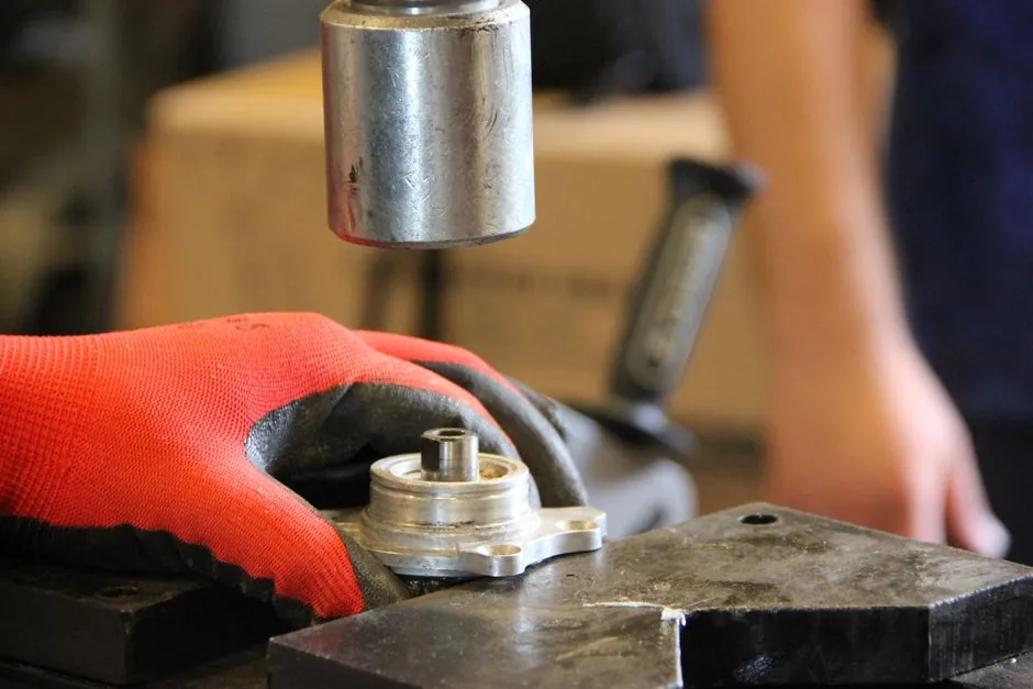
Hardware manufacturers picking a molding line in 2026 face three dominant process families, each with a distinct cost, tolerance, and volume profile: reaction injection molding (RIM), conventional plastic injection molding, and overmolding of a soft material onto a hard substrate [S1][S2][S3].
The decision usually starts with annual volume, part size, and the required dimensional tolerance, then narrows to mould material, cycle life, and whether the part needs inserts, threads, or a soft-touch surface. For valve bodies, spigots, brackets, fasteners, and similar hardware, the mould itself is the dominant cost line, so the process choice must be justified against the design rules of the selected mould type [S2].
Mould Anatomy: Cavity, Core, Parting Line, and Runner System
Every industrial mould is a hollowed metal block whose cavity forms the external geometry of the part, while a solid core inside the cavity forms internal holes and fluid passages, for example the channel inside a valve body [S2]. The precision of the core directly dictates the dimensional accuracy of the product's internal structure, which matters for threaded or fluid-handling hardware where bore tolerance is functional, not cosmetic [S2].
The parting line is the seam where the two mould halves meet, and its precision is critical: a large gap allows liquid raw material to overflow and form flash, which then requires extensive manual grinding and finishing; a high-precision parting line drastically reduces post-processing and boosts production efficiency [S2]. For visible hardware such as consumer-facing spigots, the parting line should also be placed in the least visible area of the part, and the underside will typically be more complex than the top, which usually carries the cleaner finish [S1].
The runner system is the network of sprues, runners, and gates that guides liquid raw material from the injection nozzle into the cavity, and its layout directly impacts material flow speed and filling efficiency; a poorly designed runner system causes incomplete filling and air bubbles, both of which are reject categories on a hardware production line [S2].
Process Comparison: RIM vs Plastic Injection vs Overmolding
RIM is built for large, complex parts with relatively low internal stress, but its tolerances are broader than conventional injection molding: typical linear shrinkage is 0.004-0.006 inch per inch (0.1-0.15 mm per 25 mm), or 0.4-0.6%, with a dimensional tolerance of about +/-0.010 inch per inch (+/-0.25 mm per 25 mm), so features that need precision fits must be machined or use inserts [S1]. RIM also accommodates wall thicknesses up to roughly 1 inch (25 mm) without sink, while the ideal wall range for most parts is 0.125-0.250 inch (3-6 mm); uniformity matters because consistent walls cool evenly and reduce warping [S1].
Plastic injection moulds are machined from hardened tool steel and are designed for millions of injection cycles on common thermoplastics such as ABS, Nylon, and PP, making them the default for high-volume hardware where amortised mould cost is the smallest line item per part [S2]. Die casting moulds, by contrast, run molten non-ferrous metals, primarily aluminum and zinc alloys, in high-grade H13 tool steel, and they sit between plastic injection and investment casting in both cycle life and per-part cost [S2].
Overmolding is not a standalone process but a multi-material injection cycle in which a substrate (often ABS) is partially or entirely enveloped by an overmolded material, typically a thermoplastic elastomer (TPE) such as TPE-V, TPE-U, TPE-E, or TPE-A, to add grip, sealing, vibration damping, or chemical resistance without a secondary assembly step [S3]. The two main variants are soft material over hard (TPE on ABS) and hard material over hard (a second rigid plastic or a metal insert), and the choice is driven by whether the value-add is ergonomic, decorative, or structural [S3].
Selection Criteria: Volume, Tolerance, Material, and Insert Strategy
For high-volume, tight-tolerance hardware parts under about 200 g in ABS, PP, or Nylon, hardened tool steel plastic injection moulds remain the lowest cost-per-part option because the mould amortises across millions of cycles [S2]. The penalty is upfront: mould manufacturing cost is extremely high, lead time is long, and design changes after cut steel are expensive, so the part geometry must be frozen before tooling release [S2].
For large, thick-walled, low-stress housings or enclosures where the volume does not justify hard tooling, RIM in polyurethane or polydicyclopentadiene (pDCPD) is the practical choice; pDCPD is commonly used for hardware that needs impact resistance and thermal stability, while foamed RIM grades target lightweight panels [S1]. Where the part also needs metal threads, frames, or reinforcing plates, embedding those inserts during the RIM pour removes assembly steps and increases part strength, a one-shot alternative to a multi-part mechanical assembly [S1].
For any hardware part that needs a soft grip, a seal, or electrical insulation, overmolding a TPE such as TPE-V or TPE-U onto an ABS or rigid-polymer substrate collapses two operations into one cycle and removes a glue or mechanical-fastener step; the same logic applies to insert molding of a metal bushing into a plastic body, which is a special case of hard-over-hard overmolding [S3]. Temperature resistance of both the substrate and the overmolded layer is a fundamental selection criterion, because the second-shot melt must bond to the first-shot surface without distorting it [S3].
Mould Materials, Service Life, and Cost Profile
Hardened tool steel plastic injection moulds are extremely expensive to machine but deliver millions of cycles, which is why they dominate any hardware part produced in annual volumes above roughly 50,000-100,000 units [S2]. Die casting moulds in H13 tool steel are similarly robust but are matched to molten aluminum and zinc alloys rather than thermoplastics, so the mould material, the injection parameters, and the cooling layout all differ from a plastic tool [S2].
Aluminum tooling is common in lower-volume plastic and precision metal casting because it machines faster than tool steel, but it does not match tool steel for cycle life on abrasive or glass-filled compounds, so the cost saving must be weighed against mould longevity and part surface finish [S2]. For RIM, the mould material is typically selected for thermal management rather than wear, since the reactive mixture cures rather than abrasively flowing, which is why RIM moulds can be built from lower-hardness metals and still produce large parts economically [S1].
Design Rules That Drive Mould Selection

Wall thickness uniformity is the single most important design rule for RIM, because thick sections sink and uneven sections warp; the standard mitigation is to add ribs, corrugations, or stepped profiles instead of increasing wall thickness, with ribbed walls adding stiffness without the sink risk of a thickened flat wall [S1]. For plastic injection moulds, the analogous rule is to keep walls within the material's recommended flow length-to-thickness ratio and to avoid thick-to-thin transitions that cause sink and voids [S2].
Parting line placement must be chosen together with draw direction, not after, because the mould steel is cut around the chosen parting line and a late change usually means re-cutting the tool [S1]. For overmolding, the substrate geometry must be designed so the second-shot material flows around it without air traps, and the bond between the two materials depends on chemical adhesion or mechanical interlock engineered into the substrate surface [S3].
Use Cases and Limitations in Hardware Manufacturing
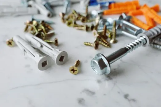
RIM fits large, low-volume housings, equipment enclosures, and impact-resistant panels where the broader tolerance and the 0.4-0.6% shrinkage are acceptable; it is not the right process for small precision parts, threaded fasteners, or any feature that must hold a sub-0.25 mm per 25 mm tolerance without post-machining [S1]. Hardened-steel plastic injection is the right choice for threaded fasteners, valve bodies, gears, and small brackets where the cycle count justifies the mould cost and where the part must hold a tight dimensional spec out of the mould [S2].
Overmolding fits any hardware where a soft-touch grip, a seal, or an insulating layer adds value: tool handles, knob and lever covers, cable grommets, and pump housings with integrated seals are all common applications, and the technique is also used for insert molding of metal bushings into plastic bodies [S3]. Limitations include the need for temperature compatibility between the two materials, the higher scrap risk if the second-shot bond fails, and the requirement that the substrate be designed for overmolding from the start rather than retrofitted [S3].
Sourcing and Standards to Anchor the Decision
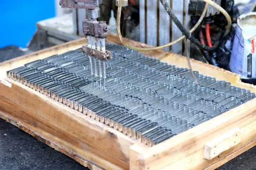
The mould itself should be sourced against a written specification that names the mould material (hardened tool steel, H13, or aluminum), the required cycle life, the surface finish, and the allowable flash and parting-line offset, because these are the variables that drive both cost and part quality [S2]. For process selection, the relevant industry references are OEM design guides for each process family, including RIM design guidelines for shrinkage, wall thickness, and inserts, and overmolding design guides for substrate and TPE compatibility [S1][S3].
Trackable signals for the next planning cycle include the release of updated OEM mould-design guides, new TPE grades qualified for higher-temperature hardware, and any published cycle-life data on H13 versus newer powder-metallurgy tool steels for die casting of hardware-grade zinc and aluminum alloys. For a related spec-first comparison of injection versus additive manufacturing on automotive hardware, see this automotive molding line selection guide; for a broader view of molding lines in a different end market, see molding line selection for agriculture machinery; and for a general primer on the production line itself, see the molding line reference page.
Detailed specification references: automatic molding line, and additive manufacturing material.