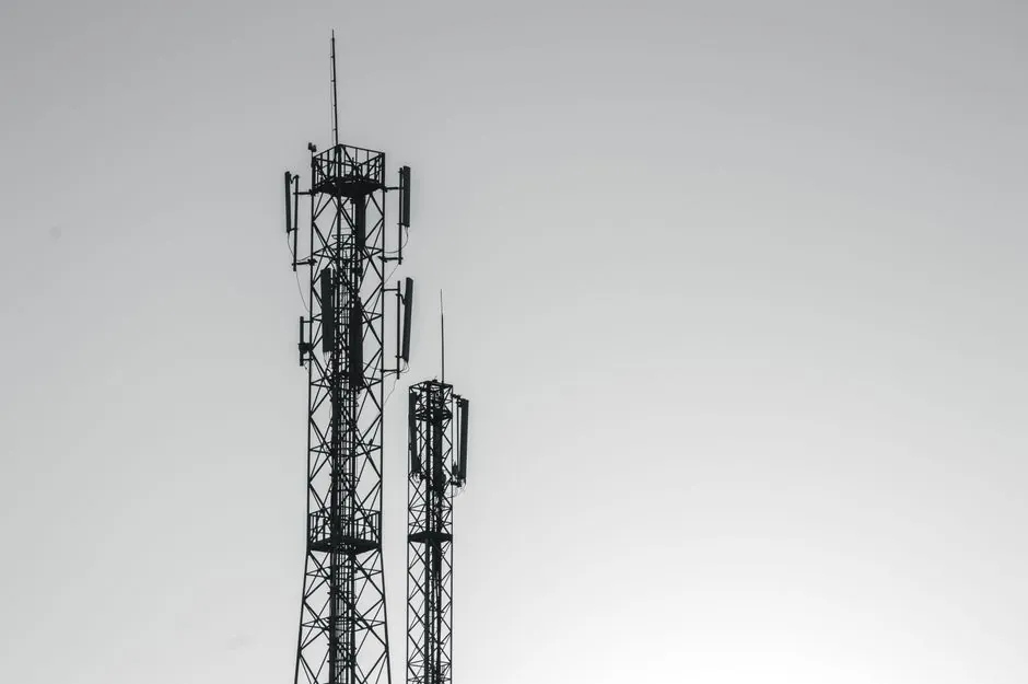
Telecom enclosures above roughly 600 mm in any single dimension with wall sections over 6 mm almost always route to a structural foam molding line, while sub-500 g covers with cosmetic Class-A surfaces still run on conventional injection molding [S3].
For outdoor radio units, fiber distribution boxes, and pole-mount cabinets, the molding line decision is driven less by tonnage than by shot weight, part volume per shift, and the need for integrated mounting bosses for cable management hardware [S1][S3].
Material and Process Pairing for Telecom Housings
PC/ABS and glass-filled PC remain the dominant enclosure materials for indoor telecom housings because they balance impact strength, appearance, and processability, while UV-stabilized PC and PA66-GF are specified for outdoor pole-mount and rooftop enclosures that see continuous sunlight [S1]. Structural foam molding with the same base resins reduces part weight by 10 to 30 percent and eliminates sink marks over thick sections, which is why it is favored for large cabinet bodies above roughly 4 kg finished part weight [S3].
For battery and power-supply compartments inside telecom enclosures, PBT and glass-filled PA are common because of dimensional stability and electrical insulation behaviour, while PP is reserved for lightweight indoor covers where chemical resistance matters more than stiffness [S1].
Selecting a Molding Line Architecture
An automatic molding line for telecom enclosures typically pairs a 250 to 850 ton clamp press with a mold-side material handling package, whereas larger structural foam cabinets push into 1000 to 2500 ton presses with nitrogen-assisted barrel expansion [S3].
The core decision axis is shot weight versus cosmetic class: telecom covers with visible Class-A surfaces need conventional injection molding with high-flow PC/ABS grades, while hidden structural housings with rib-heavy geometry benefit from structural foam with chemical or nitrogen blowing agents to suppress sink over bosses [S1][S3]. The same logic applies when comparing a shell molding machine approach for metal telecom brackets, but for plastic housings, foam versus compact injection is the dominant fork.
Core Design Rules That Drive Line Choice
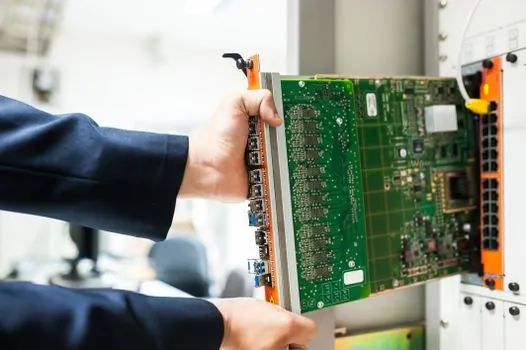
Wall thickness consistency is the single most consequential rule: variations above roughly 0.8 mm between adjacent sections cause sink marks around bosses and warpage on flat covers, and that risk rises sharply when the part is intended as a weatherproof telecom housing [S1]. For structural foam, the rule relaxes toward 6 to 12 mm uniform wall because the gas expansion tolerates thicker sections, while injection-molded telecom covers should stay in the 1.5 to 3.5 mm uniform-wall range to keep cycle time and warpage in check [S1][S3].
Draft angle, gate location, and ejector layout must be reviewed before tooling steel is cut, not after first sample, because telecom enclosure mold revisions after first article typically cost 20 to 40 percent of initial tooling when cosmetic Class-A requirements force steel rework [S1]. Rib-to-wall ratios around 0.4 to 0.6 keep sink and warpage in band, and integrated mounting bosses for cable-management hardware need to be designed with the same ratio, or the part will shrink unevenly and crack during temperature cycling on outdoor poles [S1][S3].
Insert Molding and Sealing for Telecom Hardware
Insert molding is now standard for telecom enclosures that need threaded brass inserts, heat-set captive nuts, or overmolded gaskets in a single shot, and current production lines integrate this directly with the injection cell to avoid secondary pressing [S2]. For waterproof IP65 and IP67 telecom housings, the gasket groove and seal surface must be designed as one package with the parting line location, because a 0.2 mm flatness deviation on the parting face will leak under outdoor thermal cycling even when the gasket compound is correct [S1].
Precision injection molding with insert capability is being deployed for electronics manufacturers that need custom overmolded gaskets, EMI shielding gaskets, and integrated connector boots in a single cycle, which removes a manual assembly step and cuts the leak-rate failure mode by an order of magnitude versus two-shot hand assembly [S2].
Mold Surface and Cosmetic Package

For telecom enclosure skins that face customers on a street cabinet, the mold surface, parting line, gate mark, ejector mark, and texture must be specified as a single cosmetic package, because any one of these features can downgrade the visible surface and force hand-finishing that adds cost per part [S1].
Insert-molded electronic protection covers follow the same rule: the gate must be hidden on a non-show surface, the ejector pins should land on a boss pad, and the texture should be specified with a SPI mold finish standard or an MT/VDI comparator number so that procurement and the mold shop cannot drift on interpretation between RFQ and first article [S1][S2].
Comparison: Structural Foam vs Precision Injection for Telecom Enclosures
On part weight, structural foam delivers 10 to 30 percent mass reduction versus a compact injection part of the same stiffness, which is the reason most large telecom cabinet bodies over roughly 4 kg finished weight route to foam [S3]. On surface quality, compact injection still wins, with SPI-A2 to SPI-A3 finishes reachable on PC/ABS, while structural foam typically tops out at textured SPI-C1 to SPI-C3 finishes acceptable for hidden structural skins [S1][S3].
On tooling cost, structural foam molds are roughly 15 to 25 percent cheaper per kilogram of shot weight than compact injection molds of the same tonnage, because the gas expansion tolerates thicker walls and lighter tool steel sections, while cycle time is roughly 10 to 20 percent longer for foam because of the longer cooling phase on the expanded cell structure [S3]. For telecom OEMs weighing the two routes, the practical answer is: foam for structural cabinet bodies and large pole-mount housings, precision injection for visible covers, battery doors, and small fiber distribution boxes.
When Molding Line Selection Goes Wrong

The most common failure mode is choosing a conventional injection press to mold a 6 to 12 mm thick cabinet wall: the result is sink around every boss, warpage on the sealing face, and a leak path under IP testing, which is exactly the scenario that structural foam was designed to eliminate [S3]. The opposite failure is sending a sub-500 g cosmetic telecom cover to a foam line, which produces a rough, low-density skin that fails the Class-A surface requirement and forces secondary spray painting [S1][S3].
For telecom enclosures with integrated cable-management features, the mold must be reviewed for ejector pin layout before the first sample is cut, because retrofitting ejector positions after steel is cut typically costs 20 to 40 percent of the original tooling budget and pushes first-article dates by 6 to 10 weeks [S1]. Teams that route selection through a static-pressure molding machine workflow for large sand-core metal telecom brackets face a different constraint set, but the underlying rule is the same: match the process to wall section and surface requirement, not the other way around.
The next trackable signal is whether your shortlisted OEM has published first-article dimensional and cosmetic reports for outdoor telecom enclosures, since that data is the only defensible input for a sourcing decision. Watch for revised tooling lead-time numbers from structural foam mold shops through the second half of 2026, and confirm whether a conveyor sorting line is being bundled with the molding cell or quoted as a separate downstream package.
For related coverage, see Degassing & Refining Unit Selection for Rail Components.