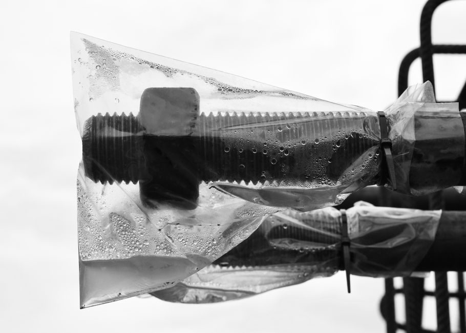
A correctly written RFQ line for a needle valve on a steam condensate duty lists, in this order: service fluid state, body and trim material, end connection, pressure class, temperature limit, Cv, seat/seal type, and actuation — because every parameter downstream depends on whether the line carries sub-cooled condensate, saturated liquid, or two-phase flash steam at the valve inlet.
Needle valves throttle via a tapered stem against a small orifice, which is why they are chosen for instrument-root isolation, gauge vents, and condensate drain trim rather than for line duty. For steam-condensate service the valve must tolerate water-hammer surges, dissolved oxygen pitting, and intermittent two-phase flow, so material and pressure class decisions matter more than on a clean gas instrument line.
Service State and Material Selection
Condensate lines present three states a buyer must declare on the RFQ: sub-cooled liquid below 100 °C, saturated liquid near line pressure, and two-phase flash steam where a pressure drop downstream of the trap vaporises a fraction of the flow [S10]. Material follows that state — 316 stainless steel wetted parts are the safe default for any line carrying dissolved O₂ or returning condensate at above ~80 °C, while nickel-plated brass (e.g. C37700) is acceptable for low-pressure HVAC condensate drains below 120 °C and 125 psi [S5][S10].
For instrument-air and analyser-sample lines, brass and 303 stainless miniature bodies rated 34.7 bar (503 psi) at DN up to 1.5 mm are common, with 10-32 UNF thread ports and metal-to-metal seats that hold positive shut-off down to 25 in Hg vacuum [S1]. Where sample corrosives are present, PVDF / PTFE wetted bodies rated 4 bar at 80 °C are specified (M&C RV-11-P pattern) [S3]. Specifying the wrong material — brass on a 150 psi saturated condensate line at 185 °C — is the single most expensive requote trigger because the body dezincifies and the seat gall within months.
Pressure Class, Temperature Limit, and Connection
Pressure class on the RFQ must be the line's design pressure, not the working pressure, with a 1.5× safety margin for condensate systems that see water-hammer transients. The published envelope runs from 125 psi on micro-pattern brass needle valves (MNV-1, 10-32 UNF porting) [S5] up to 10,000 psi with a 538 °C upper limit on heavy monoflange instrument isolation valves designed to ASME/ANSI piping class [S2].
End connection drives both leak path count and weight: threaded NPT (e.g. G 1/4" female ISO, 1/4" NPT) is the default for condensate gauge-root and trap-bypass duty, while monoflange (single forged body carrying primary isolation and vent in one piece) cuts potential leakage paths on higher-class instrument take-offs [S2][S3]. On a condensate line the buyer should also state whether the valve is screwed directly into a weldolet (cold, non-cycling) or into a hot tapping point (thermal cycling) — that decision controls whether a stainless body is mandatory regardless of the corrosion argument.
Flow Characteristic and Cv
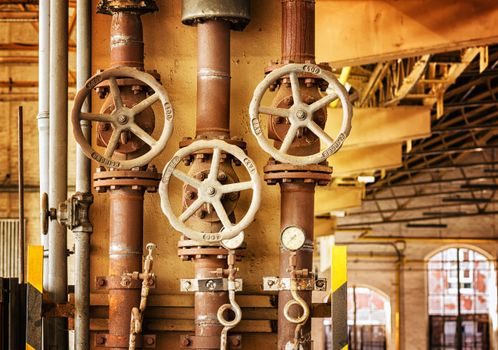
Cv (gallons per minute at 1 psi drop) must be specified for throttling duty, omitted only for pure isolation. A high-flow needle with 0–1.5 mm effective orifice delivers roughly 0–3 SCFM air at 50 psig in a 10 g miniature brass body; a high-resolution version with the same 0.8 mm travel needs ~8.25 turns shut-to-open versus ~2.25 turns for a standard needle, which matters for fine trim on a condensate bypass [S1].
For liquid condensate the rule of thumb is to size Cv for the design mass flow at the expected ΔP, then verify the vena-contracta velocity stays below 6 m/s to avoid cavitation damage on the seat — a parameter most RFQ templates omit and that forces an engineering back-and-forth. The needle valve's near-linear relationship between stem travel and orifice area in the lower lifts, and an equal-percentage tendency at higher lifts, also means the RFQ should declare whether the valve modulates or only isolates, because modulating service needs a finer-pitch stem thread and a documented number of turns lock-to-lock.
Seat, Seal, and Leakage Class
Seat material for condensate is metal-to-metal (stainless stem against stainless seat) for temperatures above ~200 °C, and PTFE or PEEK soft seat for sub-saturated duty below 150 °C where bubble-tight shut-off is required [S1][S4]. For analyser and clean-sample loops, PTFE seats inside a PVDF body give high gas-tightness at 4 bar / 80 °C with documented analytical neutrality [S3].
Leakage class must be named on the RFQ: Class IV, V, or VI per the relevant FCI/ANSI seat-leakage standard if modulating throttling is intended, or "bubble-tight" if the valve acts as an isolation block valve ahead of a steam trap or steam separator on the condensate return. Metal seats that achieve positive shut-off down to 25 in Hg vacuum are the correct choice when the same valve also serves as a gauge-root bleeder [S1].
Comparison of Common Needle-Valve Constructions for Condensate Duty
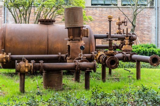
Three construction patterns dominate RFQs for condensate trim, and the choice is a trade-off between cost, leak path count, and pressure/temperature ceiling. Brass miniature threaded bodies (MNV-1, NV series) are the lowest-cost option at 125 psi and modest temperatures, with 10-32 UNF or 1/4" NPT porting and metal-to-metal seats rated to roughly 500 psig on stainless variants [S1][S5]. 316 stainless monoflange needle valves (Budenberg 6MNB / 6MN pattern) sit at the top of the range with 10,000 psi and 538 °C capability, ASME/ANSI B16.34 piping-class compliance, and a one-piece body that collapses primary isolation and vent into a single forging [S2]. Corrosion-resistant thermoplastic needle valves (M&C RV-11-P, Aalborg VCL-TT-OA) sit in the middle for low-pressure, low-temperature, high-purity duties with PEEK, PTFE, PVDF, or anodised-aluminium wetted parts and DN 3.175 mm orifices at 4–5.2 bar [S3][S4].
On a steam-condensate line the brass option is acceptable only for sub-120 °C return-line gauge roots; the 316 stainless monoflange is the correct pick anywhere the line ties into a live steam header or a hot condensate return; the thermoplastic pattern is reserved for clean-sample analyser loops on the condensate side, not for the process line itself. Dymax Model 400 and Model 485 pneumatic needle valves are a separate category — precision dispense of low- to high-viscosity fluids, not steam-condensate throttling, and should not be cross-specified on a process RFQ [S6][S8].
What the RFQ Line Must Declare to Avoid Requotes
A specifier-side audit of failed condensate needle-valve RFQs shows the same omissions every time: no declaration of whether the fluid is single-phase liquid or two-phase flash, no Cv or turn-count requirement, no seat-leakage class, and no statement of whether the valve cycles thermally with the line or sits at ambient [S2][S10]. Each omission hands the supplier a reason to quote the most expensive interpretation and then requote when the buyer's engineer pushes back, so the RFQ template should force every one of those fields to be filled or marked "not applicable".
Optional fields that consistently trigger quote inflation when left blank are: certification to ASME B16.34 (required on every monoflange needle valve rated above 600 psi) [S2], material traceability (EN 10204 3.1 for stainless wetted parts), NACE MR0175 compliance for any sour-condensate service, and clean-for-oxygen service per relevant cleaning standards on instrument-air take-offs. Buyers who leave these out routinely receive quotes inflated by 20–40% once the supplier adds them as a change order.
Limits, Failure Modes, and When Not to Use a Needle Valve
Needle valves are not a substitute for a globe valve on a condensate drain line, and the RFQ should not route one there. Needle-geometry seats erode under sustained two-phase flow and cavitate at the vena contracta when the pressure drop exceeds roughly 25% of the inlet absolute pressure — exactly the condition that occurs across a condensate trap differential. For main condensate line isolation, a needle valve belongs on the gauge root, the trap test cock, and the bypass balancing orifice, not on the line itself. [S2]
Failure modes that show up in service and should be flagged in the RFQ's "rejection criteria" field are: galling of the stem-to-seat interface on stainless pairs that have not been specified as hard-faced (Stellite or equivalent) on the seat, dezincification of brass bodies above ~120 °C, and packing leakage where the bonnet has not been specified with graphite or PTFE packing rated to the line temperature. A buyer who wants to compare this against a ball bearing trade-off logic will recognise the same principle: the parameter that dominates service life is the one the RFQ forgot to declare.
Trackable signals to confirm a clean order: the supplier's datasheet quotes a Cv within ±10% of the RFQ's calculated value, the seat-leakage class is named with a standard number, the material certificate references the actual heat number, and the pressure-temperature envelope is plotted on a single chart covering both saturated condensate and the worst-case flash-steam condition. When all four appear on the returned datasheet without prompting, the spec was written correctly.