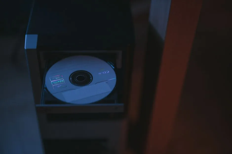
An optical rotary encoder converts shaft rotation into electrical pulses by passing LED light through, or reflecting it off, a patterned code disc and reading the modulated intensity with a photodiode or phototransistor array [S1][S2].
The two structural variants are transmissive (LED and photodetector on opposite sides of a slotted disc) and reflective (LED and photodetector on the same side, reading a metallised/printed pattern) [S1][S2]. Industrial units typically reach resolutions in the thousands of counts per revolution, with research-grade absolute prototypes demonstrated at 0.1° resolution and ±1° accuracy [S4].
Code disc: material, pattern, and how the marks are read
The code disc is a precision substrate carrying either radial slits (transmissive) or alternating reflective/absorbing tracks (reflective), commonly made from metal for industrial robustness, resin for low-cost consumer use, or glass when high resolution and low thermal expansion are required [S2]. As the shaft turns, the disc alternately blocks and passes the LED beam, producing a pulsed optical signal that the photodetector converts to a digital square wave counted in counts per revolution (CPR) [S5][S2].
In an absolute encoder, the disc carries a unique code word at every position (binary or Gray), and a multi-track photodetector reads all bits in parallel, so a single shaft angle is uniquely identified even after power loss [S4][S3]. Research work published in Sensors and Actuators A (2016) replaced the conventional coded pattern with a single transparent/semi-transparent disc segment read by a circular photodetector array, achieving 0.1° resolution and ±1° accuracy at substantially lower cost than Gray-coded discs [S4].
Photodetector stack: LED, optics, and sensor semiconductor
Most encoders use an infrared LED as the emitter because it is inexpensive and pairs well with silicon photodiodes; for high-resolution applications, laser diodes or short-wavelength coloured LEDs are substituted to suppress light diffusion through narrow slits [S2]. A convex lens collimates the otherwise diffuse LED output so the beam crosses the disc as a parallel ray, and a fixed slit is often placed opposite the code wheel to sharpen the rising and falling edges of the transmitted pulse [S2].
The receiving element is typically a silicon photodiode, phototransistor, or photodiode array made from Si, Ge, or InGaP, selected for switching speed and spectral match to the LED peak wavelength [S2]. In transmissive designs, the photodiode simply registers the presence or absence of light through each slit, while in reflective designs it captures the LED return bounced off the metallised track and rejects ambient light through modulated excitation and synchronous detection [S1][S2]. For deeper background on how the resulting electrical channels are decoded, the rotary encoder reference page covers quadrature and index-pulse handling.
Transmissive versus reflective: trade-off table

The transmissive layout sandwiches the disc between LED and sensor, giving high signal amplitude and straightforward optics, which is why it dominates high-CPR industrial encoders and is the natural choice for linear encoder glass scales where the strip is read through optical glass [S1][S2]. The reflective layout mounts LED and photodetector on the same PCB (or even the same die), so the encoder package can be thinner and significantly smaller, at the cost of a weaker return signal that demands careful photodetector alignment and lower-noise analogue front ends [S1][S2].
Selection by criterion, with sources: Resolution ceiling, transmissive (glass disc, fine slits) > reflective (limited by track photolithography) [S2]; Vibration and temperature tolerance, metal disc > resin, glass intermediate [S2]; Package height, reflective wins because no through-beam path is needed [S1]; Assembly cost, reflective enables chip-on-board stacking and fewer parts [S2]; Signal-to-noise ratio, transmissive wins because the full LED output reaches the photodiode without a diffuse reflection loss [S1][S2].
Incremental versus absolute output, and where each is used
An incremental encoder outputs two quadrature channels (A and B, 90° out of phase) plus an optional index Z pulse once per revolution, and position is obtained by counting pulses from a known reference; resolution is set by the number of slits or reflective lines on the disc and is commonly expressed in CPR or pulses per revolution (PPR) [S5][S3].
An absolute encoder outputs a unique digital word for every shaft angle within one revolution (single-turn) or across many revolutions (multi-turn, typically with an additional gear or battery-backed turns counter), so position is valid immediately on power-up without homing [S3][S4]. Industrial applications that demand loss-of-power position retention, such as robotic joint axes, CNC rotary tables, and steering-angle sensors, therefore specify absolute encoders even at higher cost, while simple speed feedback and conveyor-length measurement are well served by incremental units [S4][S3].
Failure modes, environmental limits, and reliability checks
Because the optical path is open, the dominant failure modes are contamination (oil mist, coolant, dust) depositing on the code disc or photodetector window, LED ageing reducing signal margin, and disc runout from bearing wear causing pulse-to-pulse jitter [S3][S5]. In harsh environments, sealed housings (IP65/IP67) or stainless-steel bodies (e.g. models 802S, 858S) are specified, while intrinsically safe variants following the EX cube housing pattern serve hazardous areas [S5].
Acceptance checks that catch most field issues: verify supply voltage and output current against the datasheet (5 VDC, 12-24 VDC, or 4.5-30 VDC wide-range supplies are common in the Model 711/715/716 industrial line) [S5]; confirm quadrature phasing with an oscilloscope on both channels; check index pulse width (typically 90° electrical, gated or ungated); and run a vibration sweep if the encoder is mounted on a motor with significant radial load, since resonance in the disc plane is a real failure driver in motor-feedback installations [S5][S3]. Specifications on the disc coupling page are useful here because shaft misalignment from a stiff coupling is a common source of premature bearing failure that masquerades as encoder noise.
Selection checklist for a process engineer
Step 1, define resolution: state CPR needed, including any electronic multiplication (×4 quadrature), and confirm the disc material and LED type can deliver it; glass discs with laser-diode sources are the only realistic path above roughly 10,000 CPR [S2]. Step 2, define output protocol: incremental line driver (RS-422, TTL, HTL) for servo feedback, SSI/BiSS/EtherCAT/PROFINET for absolute multi-turn fieldbus, or parallel grey-code for legacy controllers [S3][S5].
Step 3, define environment: temperature range (industrial -40 °C to +85 °C is common, with some extended-range units to +100 °C or higher), IP rating, vibration and shock (often 10 g vibration, 100 g shock per industrial datasheets), and whether the area is hazardous (EX-rated housing required) [S5]. Step 4, define mechanical interface: shaft vs hollow-bore vs hub-shaft, NEMA frame size, and coupling type, noting that a code reader used for traceability on the same line has different mounting and cabling constraints and should be specified on its own bill of material. Finally, step 5, confirm the manufacturer provides a CPR cross-reference, MTBF figure, and a vibration spectrum, all of which are standard deliverables from US and EU encoder suppliers such as Dynapar, Encoder.com, and the FAULHABER reflective encoder family used in small precision motors [S1][S5].
Trackable next signals to watch over the next two quarters: industry migration from TTL/HTL push-pull outputs to RS-422 line drivers in mid-tier motor feedback, continued miniaturisation of reflective encoders into sub-10 mm packages for collaborative robot joints, and wider adoption of on-chip photodetector arrays in place of discrete Si photodiodes, all of which would push incremental CPR ceilings higher without changing the basic disc-and-photodetector architecture described here [S1][S2][S3].
See also our earlier report, OIML R60 nmax and vmin: how load cell verification intervals are set.