A code reader is an industrial machine-vision device that captures and decodes printed and direct-marked codes, from 1D linear barcodes to 2D Data Matrix and QR symbols, turning a physical mark into a digital identity for traceability, sorting, and process control. In factory and logistics usage the term "code reader" usually means a fixed-mount, image-based unit installed over a conveyor or workstation, as distinct from a handheld scanner. Two names appear on most purchase orders: "barcode scanner" for laser-line 1D devices, and "code reader" or "ID reader" for the camera-based readers that also handle 2D and direct part marking (DPM).
This guide treats the modern image-based code reader as the reference case. It covers how reading technology, symbology coverage, optics, illumination, and ISO/IEC code-grading standards combine into a selection decision, with verified parameter ranges and real manufacturer series so procurement and design engineers can specify a reader without guesswork.
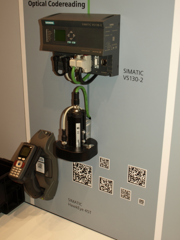
Photo: StraSSenBahn, CC BY 3.0, via Wikimedia Commons
This guide is written for industrial purchasing engineers and design engineers. Across 6 chapters it covers reading technologies, code symbologies, sensor and optics specifications, illumination and DPM, the spec parameters that decide selection, and the decision sequence itself, with 7 selection FAQs and manufacturer comparisons. All code-quality and symbology references trace to public ISO/IEC standards, including ISO/IEC 15415 and 15416 (print-quality grading), ISO/IEC TR 29158 (DPM grading), ISO/IEC 16022 (Data Matrix), ISO/IEC 18004 (QR Code), and ISO/IEC 15417 (Code 128).
Chapter 1 / 06
What Is a Code Reader
A code reader is an automatic identification device that locates a printed or marked code within its field of view, captures it optically, and decodes the encoded data into a character string the control system can act on. It sits in the machine-vision and ID family alongside vision systems, smart cameras, and laser markers, and it is one of the most deployed devices in modern manufacturing and logistics because nearly every traceable part, carton, or label now carries a machine-readable symbol. The reader is the bridge between the physical mark and the digital record: scan a Data Matrix on an engine block, and a unique serial flows into the manufacturing execution system that follows that block through every downstream station.
Functionally a code reader has four stages: image acquisition, where a lens forms an image of the code on a sensor under controlled illumination; localization, where algorithms find the symbol and its finder pattern within the frame; decoding, where the dark and light modules are sampled and run through the symbology rules and error correction to recover the data; and output, where the decoded string plus a read or no-read status is delivered over a network or I/O interface. What distinguishes an industrial code reader from a consumer phone-camera scan is reliability under adverse conditions: motion, vibration, ambient light swings, oil and dust on the code, and codes marked directly into metal rather than printed on white paper.
The lineage of automatic identification runs from the first scanned retail UPC barcode in 1974, through laser scanners that swept a beam across linear codes in the 1980s, to the arrival of 2D matrix symbologies. Data Matrix and QR Code in the 1990s allowed far more data in a smaller area and survived partial damage through Reed-Solomon error correction, which made permanent marking of small parts practical. As CMOS image sensors and embedded processors became cheap and fast, image-based readers displaced laser scanners for 2D work, and direct part marking pushed readers to add sophisticated lighting and decode algorithms tuned for low-contrast, textured marks.
In terms of deployment scale, a code reader may sit anywhere from a single benchtop station verifying a label print to dozens of readers arrayed in a tunnel over a high-speed parcel sorter reading every face of a carton at several meters per second. Each application maps to a different combination of resolution, field of view, working distance, illumination, and interface, which is precisely why selection is an engineering exercise rather than a catalog pick. A reader that excels at reading crisp printed labels on slow lines can fail completely on a laser-etched Data Matrix on a curved, shiny metal shaft, and the reverse is equally true.
Four engineering metrics ultimately determine whether a code reader earns its place: read rate (the percentage of presented codes decoded on the first read), decode speed and throughput, robustness to code quality and environment, and integration fit with the line's triggering and network. A reader with a 99.9 percent first-pass read rate quietly disappears into the process; one stuck at 95 percent generates a no-read every twenty parts, forcing manual rework that erodes line efficiency and, in regulated industries, breaks the traceability chain. The cost of a missed read almost always dwarfs the price difference between an adequate reader and the right one.
Chapter 2 / 06
Reading Technologies and Form Factors
Two reading technologies and several form factors define the market. The first technology split is between laser scanning and image-based reading. A laser scanner projects a single focused beam and uses a rotating mirror or oscillating element to sweep it across a linear barcode, measuring reflected intensity to recover the bar-and-space pattern. An image-based reader behaves like a purpose-built industrial camera: it captures a full two-dimensional frame on a CMOS sensor and runs decode software on the image. The consequences are significant. Laser scanners, the basis of the classic industrial barcode scanner, read only 1D codes and depend on a moving optical part, but they reach long distances and tolerate low ambient light. Image-based readers read 1D, stacked, and 2D codes in any orientation, have no moving parts so they resist shock and vibration, and decode damaged, distorted, or low-contrast codes far better, which is why they dominate modern 2D and DPM applications.
Technology
Code Types
Moving Parts
Strengths
Typical Use
Laser scanner
1D only
Yes (mirror)
Long range, low-light tolerant
Linear-code logistics, legacy lines
Linear CCD imager
1D, stacked
No
Durable, contact-range 1D
Label scanning at short range
2D area imager
1D, 2D, DPM
No
Omnidirectional, damage-tolerant
Factory traceability, mixed codes
The omnidirectional advantage of area imaging deserves emphasis. A laser line must be roughly aligned with the bars to read a 1D code, which on an automated line means the part must be oriented or the reader gimbaled. A 2D area imager captures the whole symbol and locates its finder pattern algorithmically, so it reads regardless of rotation. For 2D matrix codes this is essential: a Data Matrix carries no preferred reading direction, and the reader must find its L-shaped finder pattern and clock track anywhere in the frame. Cognex describes its 1DMax algorithm as optimized for omnidirectional 1D reading and its 2DMax with PowerGrid as able to decode 2D codes even with substantial damage to or loss of the finder or clocking pattern.
The second axis is form factor. Fixed-mount (stationary) readers are bolted over a conveyor or workstation and read automatically as parts pass, triggered by a sensor or software. They are the focus of this guide. Handheld readers are operator-aimed and triggered for picking, receiving, and ad-hoc verification. Smart-camera-style readers blur into general machine vision when the same hardware also performs inspection. Within fixed-mount, readers range from compact, self-contained units with integrated optics and lighting (Datalogic Matrix 220, Keyence SR-2000) to higher-resolution platforms with interchangeable lenses and external lighting for demanding fields (Cognex DataMan 370, SICK Lector63x).
Decode intelligence increasingly differentiates readers. Beyond the core symbology rules, vendors layer algorithms that reconstruct degraded codes, suppress glare, and auto-tune exposure and lighting. Several lines now apply onboard machine learning or AI: Datalogic markets its Matrix 220 XAI as AI-powered for DPM with auto-setup, and Cognex offers AI-based decode in its newer DataMan series. These algorithms matter most exactly where simple thresholding fails: low-contrast laser marks on shiny metal, dot-peen codes with uneven dot placement, and printed codes smeared or partially torn in handling. The practical takeaway is that two readers with identical sensors can post very different read rates on the same hard codes because of decode software, so the only honest comparison is a trial read on your actual parts.
Chapter 3 / 06
Code Symbologies and Standards
A code reader is only as useful as the symbologies it decodes, and each symbology is defined by an ISO/IEC specification that fixes its structure, character set, and error correction. Symbologies fall into three families: 1D linear codes, stacked codes, and 2D matrix codes. Knowing which family a code belongs to immediately constrains the reader technology, because a laser scanner can only ever read 1D linear codes while 2D matrix codes demand an area imager. The table below compares the most common industrial symbologies, their governing standard, and their data character.
Symbology
Family
Standard
Typical Use
Code 128 / GS1-128
1D linear
ISO/IEC 15417
Logistics labels, GS1 shipping
Code 39
1D linear
ISO/IEC 16388
Industrial part numbers
EAN / UPC
1D linear
ISO/IEC 15420
Retail point of sale
PDF417
Stacked
ISO/IEC 15438
ID cards, shipping manifests
Data Matrix ECC200
2D matrix
ISO/IEC 16022
Part marking, electronics, DPM
QR Code / Micro QR
2D matrix
ISO/IEC 18004
Consumer links, asset tags
1D linear codes encode data in the relative widths of parallel bars and spaces along one axis. Code 128 (ISO/IEC 15417) is the dense, full-ASCII workhorse of logistics, and its GS1-128 variant carries structured application identifiers for the supply chain. Code 39 (ISO/IEC 16388) is older and lower density but rugged and self-checking, common on industrial part numbers. The retail EAN/UPC family (ISO/IEC 15420) is fixed-format and optimized for point of sale. All 1D codes share a weakness: they hold little data, are read along one direction, and a single torn bar can defeat the read because they carry minimal error correction.
Stacked codes such as PDF417 (ISO/IEC 15438) stack many short 1D-like rows to raise capacity while staying readable by a scanning device with vertical tolerance. PDF417 appears on identity documents and shipping manifests where hundreds of bytes must fit a rectangular space. It carries Reed-Solomon error correction, so it tolerates some damage, but it remains larger than a true matrix code for the same payload.
2D matrix codes encode data in a grid of dark and light cells read in two dimensions, packing far more data into far less area. Data Matrix ECC200 (ISO/IEC 16022) is the dominant factory symbology: its L-shaped finder pattern and clock track let a reader locate and sample it in any rotation, and its Reed-Solomon error correction reconstructs the full message even when roughly 30 percent of the symbol is damaged, which is why it survives marking directly into scratched, oiled metal parts. QR Code and Micro QR (ISO/IEC 18004) offer selectable error-correction levels and fast omnidirectional finder patterns, dominating consumer and asset-tag use. GS1 governs how application identifiers are encoded inside Data Matrix and QR for traceability, and the GS1 DataMatrix carrying a medical-device UDI is a regulated example. When specifying a reader, list every symbology and variant present on your parts, including GS1 composites and any rectangular Data Matrix, because decode support is per-symbology and not universal across firmware versions.
Chapter 4 / 06
Optics, Illumination, and DPM
Once symbology coverage is settled, the physical read depends on optics and lighting matched to the code and the part. The three optical variables are field of view (FOV), working distance, and depth of field. The FOV is the area the sensor images at a given distance and must contain the code plus the tolerance band of where the part actually presents. Working distance is the lens-to-code separation, set by the lens and focus configuration. Depth of field is the range of distances over which the code stays in acceptable focus, which matters whenever part height varies. Fixed-focus optics give the largest FOV per cost; variable focus, especially electronically tunable liquid lenses, lets one reader cover a span of distances.
Liquid-lens autofocus has become a defining feature of fixed-mount readers because it adds focus flexibility with no moving parts. A liquid lens holds two immiscible liquids, typically a conductive aqueous solution and an insulating oil, whose interface curvature changes when a voltage is applied, shifting focal length electronically. According to manufacturers including Cognex and Basler, a liquid lens can refocus in roughly 100 milliseconds, far faster than a motorized lens that may need seconds, so a single reader can read codes at several heights or distances on the fly. This widens usable depth of field and reduces the number of cameras a line needs.
Resolution is where optics meets symbology. The decisive metric is pixels-per-module (PPM): how many sensor pixels span the smallest code element, called the X-dimension for 1D or the cell size for 2D. As a practical floor, printed 1D and 2D codes need about 2 to 3 pixels per module and DPM codes need more, often 4 or more, because their contrast is marginal. From PPM you can size the sensor: minimum horizontal pixels equals FOV width divided by X-dimension, multiplied by target PPM. A 200 mm FOV reading a 0.25 mm cell at 3 PPM needs about 2400 horizontal pixels, which is why industrial readers cluster around 1.2, 2, 3, and 5 megapixel sensors. The table below summarizes representative fixed-mount readers and their headline specs as published by their makers.
Series
Sensor
Range / FOV
Codes
Interfaces
Keyence SR-2000
3.1 MP CMOS (2048×1536)
100–2000 mm
1D, 2D
Ethernet, EtherNet/IP, PROFINET, RS-232C, USB
Datalogic Matrix 220
1.2 MP
Compact, DPM-tuned
1D, 2D, DPM
Ethernet, fieldbus, serial
Datalogic Matrix 320
2 MP (1920×1080)
Wide 16:9 field
1D, 2D, DPM
Ethernet, fieldbus, serial
SICK Lector63x
~2 MP grayscale (1600×1200)
50–2200 mm
1D, 2D
Ethernet, EtherNet/IP, PROFINET, serial, USB
Cognex DataMan 370
High-res CMOS (multi-option)
Liquid-lens, lens options
1D, 2D, DPM
Ethernet, EtherNet/IP, PROFINET, serial
Illumination is what makes direct part marks readable, and it is the single most important DPM variable. DPM codes get their contrast from surface relief and reflection rather than ink, so lighting geometry decides whether dots and etched cells appear dark or light. Low-angle (dark-field) lighting grazes the surface so engraved cells scatter brightly against a dark background. Diffuse dome lighting wraps soft light around curved or shiny parts to suppress hot spots. Polarized illumination cuts specular glare from mirror-finished metal. These geometries may be built into the reader or supplied by an external vision light source when the part demands more than the integrated lighting can deliver. Datalogic, for example, combines red and blue models with polarized and diffused options to suit varied surfaces. The marking method drives the choice: laser-etched and dot-peen Data Matrix on metal usually need controlled low-angle or diffuse light, while flat printed labels read fine under simple front light. Because contrast is marginal, DPM-rated readers pair this lighting with decode algorithms tuned for textured marks, and the right lighting plus algorithm often matters more than raw resolution.
Chapter 5 / 06
Key Specification Parameters
Reading a reader's datasheet is a core procurement skill. Datasheets list many fields, but a manageable set truly drives selection: read performance, sensor resolution, optics and focus, illumination, decode coverage, interfaces, environmental rating, and code-quality grading capability. Each is explained below, with the standards that govern code quality treated last because they are the most misunderstood.
Read performance is usually expressed as first-pass read rate (percent of presented codes decoded on the first attempt) and decodes per second or maximum line speed. These figures are application-specific: a vendor's quoted read rate assumes a code quality and lighting they controlled, so it is a ceiling, not a guarantee. The honest metric is the read rate measured on your own parts under your own lighting and line speed during a trial.
Sensor resolution and optics together set the smallest readable code. Resolution is the pixel count (commonly 1.2 to 5 megapixels) and the optics is the lens and focus type. The derived metric that matters is the minimum cell size or X-dimension the reader resolves at your FOV and distance, governed by the pixels-per-module rule from Chapter 4. Liquid-lens autofocus adds depth-of-field flexibility, retuning focus in roughly 100 milliseconds with no moving parts.
Interfaces and triggering determine how the reader fits the control architecture. Most industrial readers expose Ethernet TCP/IP plus industrial fieldbus protocols, commonly EtherNet/IP and PROFINET, along with RS-232C serial and digital I/O for hardware trigger-in and pass/fail-out. The trigger source, a photoelectric sensor, a rotary encoder pulse, or a software command, decides when a frame is captured, and on moving lines a hardware trigger tied to the part's arrival is essential for timing and throughput.
Code-quality grading is the most subtle parameter. Some readers can report an ISO/IEC quality grade, but a reader is not a verifier. The relevant standards are:
ISO/IEC 15416: grades 1D barcode print quality on an A-to-F scale by averaging ten reflectance scan profiles across the code height; any line failing decode, minimum reflectance, or edge contrast forces an F.
ISO/IEC 15415: grades 2D matrix codes against eight parameters including symbol contrast, modulation, fixed pattern damage, axial nonuniformity, grid nonuniformity, and unused error correction, with the overall grade equal to the lowest single parameter.
ISO/IEC TR 29158: the DPM grading method (formerly the AIM DPM specification) that adapts 15415 for direct part marks with controlled lighting and metrics suited to textured surfaces.
ISO/IEC 15426: defines verifier conformance; only a 15426-conformant verifier under specified lighting produces a legally citable, repeatable grade.
Environmental and mechanical specs close the list: ingress protection (IP65 to IP67 for washdown or dust), operating temperature (often 0 to 45 degrees C for compact readers), supply voltage (typically 24 VDC), and housing and connector type. A reader that decodes flawlessly on the bench but is rated only IP54 will fail in a washdown food line, so the environment rating is as load-bearing as the optics.
Chapter 6 / 06
Selection Decision Factors
To turn the preceding chapters into a specific model, follow the decision sequence below. Most selection failures come not from one wrong answer but from deciding optics or interface before the code and the application are pinned down. These eight steps double as a fixed RFQ template.
Code inventory: List every symbology, variant, and minimum X-dimension or cell size present on the parts, including whether any are direct part marks. This single step eliminates whole categories: any 2D or DPM code rules out a laser scanner and mandates an area imager.
Field of view and presentation: Define the FOV needed to contain the code plus part-position tolerance, the working distance, and the depth of field set by part-height variation. These fix the resolution and lens or liquid-lens focus the reader must provide.
Resolution and read margin: Apply the pixels-per-module rule (at least 2 to 3 PPM for printed codes, 4 or more for DPM) to size the sensor: minimum pixels equals FOV width divided by X-dimension times target PPM. Keep margin, do not specify at the bare floor.
Illumination and DPM strategy: Match lighting geometry to the marking method: low-angle or diffuse for etched and dot-peen metal, polarized for shiny surfaces, simple front light for printed labels. For DPM, weight lighting and decode algorithm above raw megapixels.
Line speed and triggering: Compute the exposure that keeps motion blur below a fraction of the X-dimension at belt speed, decide on a global-shutter sensor or strobed light if needed, and select the trigger source: photoelectric sensor, encoder, or software.
Interfaces and protocol: Confirm fieldbus fit, EtherNet/IP, PROFINET, TCP/IP, plus serial and digital I/O for trigger and result, so the reader drops into the existing PLC or line controller without a gateway.
Quality grading need: If a customer or regulation requires graded codes (ISO/IEC 15415, 15416, or TR 29158), decide whether in-line grade reporting suffices or a 15426-conformant verifier is mandatory; do not conflate a reader's grade estimate with a verified grade.
Environment and total cost: Set the IP rating, temperature, and connector for the installation, then weigh purchase price against the cost of no-reads. A reader that saves money upfront but reads one code in twenty less will cost more in rework and traceability gaps within a single year.
One dimension teams routinely overlook is serviceability and lifecycle support: local spare-part availability, application-engineering help for first setup, firmware updates that add symbology or decode improvements, and the auto-setup tools that shorten commissioning. Datalogic, Keyence, Cognex, SICK, Omron Microscan, Zebra, and Honeywell all maintain industrial support networks, and the right partner matters most when a line that has run for years suddenly faces a new code variant or a degraded marking process. The cheapest reader that no one can support after deployment is the most expensive one to own.
FAQ
What is the difference between a code reader and a barcode scanner?
In industrial usage the terms overlap, but the distinction is about technology and code coverage. A classic laser barcode scanner sweeps a single beam across a linear 1D code and decodes the reflected light pattern, so it reads only 1D symbologies. An image-based code reader is effectively a camera with onboard decoding: it captures a full two-dimensional image and runs decode algorithms, so it reads 1D, stacked, and 2D matrix codes (Data Matrix, QR) in any rotation, including direct part marks. Most fixed-mount industrial code readers today are image-based because they have no moving mirror, resist shock and vibration, and tolerate damaged or low-contrast codes that defeat a laser line.
What symbologies and code types can a 2D code reader decode?
A modern image-based code reader decodes three families. 1D linear codes: Code 39, Code 128 (ISO/IEC 15417), Interleaved 2 of 5, Codabar, Code 93, GS1-128, GS1 DataBar, and the retail EAN/UPC family. Stacked codes: PDF417 and MicroPDF417. True 2D matrix codes: Data Matrix ECC200 (ISO/IEC 16022), QR Code and Micro QR (ISO/IEC 18004), Aztec, MaxiCode, and DotCode. Data Matrix ECC200 is the workhorse of factory traceability because its Reed-Solomon error correction reconstructs the full message even with about 30 percent of the symbol damaged, which suits parts that get scratched, oiled, or partially obscured on the line.
What is a DPM code and why does it need a special reader?
DPM stands for Direct Part Marking: a code etched or stamped permanently into the part itself rather than printed on a label. Common methods are laser etching, dot peen (a carbide pin striking dot indentations), chemical etching, and inkjet. DPM codes are hard to read because contrast comes from surface texture and reflection, not ink, so a flat front light often washes them out. DPM-capable readers add controlled lighting (low-angle, dome, diffuse, or polarized illumination) and decode algorithms tuned for dot-peen and laser marks. They are mandated in automotive, aerospace, electronics, and medical device traceability, where the GS1 DataMatrix carrying a UDI must survive the full life of the part.
How do I size the field of view, working distance, and resolution?
Three numbers drive the optics. First the field of view (FOV) must be large enough to contain the code plus part-position tolerance at the slowest line position. Second the working distance sets which lens or focus setting fits, and the depth of field must cover part-height variation; liquid-lens readers retune focus in under about 100 milliseconds to widen usable depth. Third, resolution is governed by pixels-per-module (PPM): aim for at least 3 to 4 pixels across the smallest code element (the X-dimension or cell size). Compute the minimum sensor as FOV width divided by X-dimension, multiplied by the target PPM. If that exceeds the sensor pixel count, reduce FOV, move closer, or step up to a higher-megapixel reader.
What do ISO/IEC 15415, 15416, and TR 29158 mean for code quality?
These are the print-quality grading standards a verifier applies, scoring codes A to F where A is best. ISO/IEC 15416 grades 1D barcodes: it averages ten scan reflectance profiles across the height, and any line failing decode, minimum reflectance, or edge contrast drops to F. ISO/IEC 15415 grades 2D matrix codes against eight parameters including symbol contrast, modulation, fixed pattern damage, axial nonuniformity, grid nonuniformity, and unused error correction, and the overall grade equals the lowest single parameter. ISO/IEC TR 29158 (the former AIM DPM specification) adapts 15415 for direct part marks, adding controlled lighting and metrics such as cell modulation and minimum reflectance suited to textured surfaces. A reader is not a verifier: only an ISO/IEC 15426-conformant verifier produces a legally citable grade.
How do I integrate a fixed-mount reader on a moving line?
Match exposure to line speed so the code does not blur: required exposure roughly equals the allowable motion blur (a fraction of the X-dimension) divided by belt speed, which on fast lines forces short exposures and bright illumination or a global-shutter sensor. Trigger the read with a photoelectric sensor or encoder pulse as the part enters the FOV, rather than free-running, to save processing and timestamp each read. For interfacing, most industrial readers expose Ethernet TCP/IP plus fieldbus options such as EtherNet/IP and PROFINET, with RS-232C and digital I/O for trigger-in and pass/fail-out. Add no-read handling: divert, alarm, or re-present, and log the no-read rate as a process KPI.
Which manufacturers and series fit industrial code reading?
For fixed-mount image-based reading the established suppliers are Cognex (DataMan 280, 290, and 370 series, with 1DMax and 2DMax decode algorithms and liquid-lens autofocus), Keyence (SR-2000 and SR-X series, roughly 3.1-megapixel CMOS, 100 to 2000 mm range, EtherNet/IP and PROFINET), SICK (Lector62x and Lector63x, 1.3 to 2 megapixel grayscale, EtherNet/IP and PROFINET), Datalogic (Matrix 220 at 1.2 megapixel for compact DPM and Matrix 320 at 2 megapixel for wider fields), Omron Microscan, Zebra, and Honeywell. Select on code mix (1D-only versus 2D and DPM), required FOV and resolution, illumination flexibility, and fieldbus fit, then confirm spare-part and calibration support in your region.