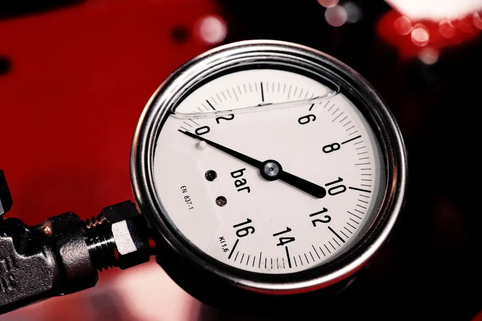
Rod buckling becomes a first-order constraint on pneumatic cylinders once the stroke-to-bore ratio passes roughly 10:1, with manufacturer buckling charts required beyond that line on standard single-rod designs [S1][S7].
Standard pneumatic systems run at 0.4–0.7 MPa (60–100 psig) per ISO 4414, so the net compressive force on a fully extended rod is large enough to bend slender rods long before any force-margin problem appears on a short-stroke machine [S9]. A 12 in. bore pneumatic cylinder produces just over 11,000 lbf at 100 psi; a 2-1/2 in. bore produces a far smaller figure, and a long stroke on that small bore is exactly the geometry that triggers buckling checks [S8].
Where the 10:1 Stroke-to-Bore Rule Comes From
The 10:1 rule is a screening threshold, not a formula: below it, rod buckling is rarely the binding constraint on a standard pneumatic rod cylinder, and above it the manufacturer’s rod-buckling chart (or an Euler calculation) becomes mandatory [S1][S7]. For example, a 50 mm bore, 500 mm stroke cylinder sits at 10:1 and is still in the routine zone; pushing the same 50 mm bore to 800 mm stroke pushes the ratio to 16:1, where the critical buckling load drops into the operating force band and demands a heavier rod or external guidance [S2][S3].
Catalog pages make the same call in their model-selection tables: SMC’s BEST technical data lists a column titled “Maximum stroke that can be used according to buckling strength” directly against each bore and mounting bracket, treating it as a first-class selection parameter rather than a footnote [S6]. The matching encyclopedia entry on pneumatic cylinder sizing covers the same force-and-stroke relationship in more general terms.
The Euler Column Math Behind the Threshold
Rod buckling is governed by the classic Euler formula Pcr = π²EI/(KL)², where E is the rod modulus, I is the second moment of area of the rod cross-section, L is the unsupported stroke, and K is the effective-length factor set by the mounting arrangement [S2]. For a 50 mm steel rod, 1,000 mm stroke, both ends pinned (K = 2.0), the critical load works out to roughly 75,800 N; if the design push is 50,000 N, the safety factor is only 1.52, which is below the margin most pneumatic systems carry [S2].
Mounting style changes K, and therefore changes the safe stroke at the same bore: a fixed–fixed mount drops K toward 0.5 and roughly quadruples the critical load, while a cantilevered mount pushes K above 2.0 and roughly quarters it [S2]. The same rod can be safe or unsafe across a stroke range depending on whether the machine frame clamps the rod end, the cap end, or both. Force is computed separately as F = P × A, with a 50 mm bore at 0.6 MPa delivering roughly 1,178 N of theoretical extend force, against which the buckling load has to be checked [S3][S9].
Real Operating Numbers Engineers Can Quote
At 0.6 MPa (about 87 psi) supply, common ISO bores deliver 251 lbf at 2 in. bore up to 1,005 lbf at 4 in. bore, with 80 psi imperial sizing tables in the same range [S1]. Typical ISO 4414 shop pressure is 0.4–0.7 MPa, and 50 mm bore at 0.6 MPa gives about 1,178 N theoretical extend, less 10–20% on retract due to the rod area and another 5–15% derated for seal friction, leaving net usable force well below the theoretical value [S3][S9].
Long, thin rods are the weak geometry: doubling the rod diameter raises the critical buckling load by a factor of 16 because I scales with d⁴, so increasing rod size is the cleanest fix when stroke cannot be shortened [S2]. A 12 in. bore pneumatic cylinder generating 11,000 lbf at 100 psi can rod-buckle quickly on a long stroke if the rod is undersized, which is why catalog charts plot critical load as a function of stroke length for each rod diameter [S6][S8]. The related pneumatic actuator selection reference frames the same force-versus-pressure trade.
Design Options Past the 10:1 Limit
Four practical moves push the buckling line back: (1) increase rod diameter, exploiting the d⁴ stiffness term, (2) change the mounting style to lower K, (3) add external guide rods or a linear bearing column to shorten the unsupported length, and (4) switch to a non-cantilevered architecture such as a rodless cylinder, a tandem cylinder, or a dual-rod design where load is shared across two columns [S1][S2][S3].
Engineers familiar with sizing also use cushion and stroke adjustments, but the physics on pre-charge or stroke limiting does not raise maximum force: P × A still caps the curve, and pre-charging only extends the distance over which that ceiling is reached [S4]. For motion control, meter-out flow control adds back pressure that subtracts from differential pressure and costs 20–40% of nominal pressure, which reduces the in-service force margin and tightens the buckling check further [S5].
Comparison: Three Fixes for a 50 mm Bore, 1,000 mm Stroke Cylinder

Take a 50 mm bore, 1,000 mm stroke, 0.6 MPa application pushing roughly 1,178 N theoretical. With a 25 mm rod, both ends pinned, the safety factor on buckling is around 1.52, marginal for any production machine [S2][S3]. Option A: double the rod to 50 mm. The moment of inertia increases sixteenfold, lifting the critical load into the hundreds of kilonewtons and pushing the safety factor well above 4, at the cost of a larger piston annulus and 10–20% retract force loss [S2][S3].
Option B: keep the rod, but switch to a fixed–fixed mount (K near 0.5). The critical load rises by a factor of 16 over the pinned case, hitting a high safety factor without changing bore, stroke, or rod diameter, at the cost of a more rigid machine frame [S2]. Option C: add an external linear guide so the unsupported L effectively shrinks to 200–300 mm; the (KL)² term drops by an order of magnitude, again clearing the buckling limit, with the trade-off being additional hardware, footprint, and a separate lubrication path [S2][S1]. On cost, Option C usually wins on parts but loses on assembly; Option A wins on simplicity but costs retract force; Option B is the cleanest when the frame design allows it.
What the Sourcing and Standards Picture Looks Like
ISO 4414 governs the pneumatic side of the system (0.4–0.7 MPa, 60–100 psig) and is the standard most engineering references cite when discussing acceptable pressure, temperature, and contamination limits for compressed-air actuators [S9]. For the rod column itself, no single ISO clause defines the buckling check; designers fall back on the Euler formulation with a K-factor from the mount and a safety factor consistent with the rest of the machine design, with manufacturer buckling charts as the first reference [S1][S2][S6].
For a clean working sketch, start with the manufacturer’s “maximum stroke vs bore” table for the chosen mounting bracket, run the Euler calculation with the right K-factor as a sanity check, and only then go to the pneumatic cylinder overview for general system context. For background on the broader actuator category, the pneumatic actuator datasheet parameters reference covers how bore, pressure, and cushion volume interact in vendor catalogs.
Failure Modes and Field Signals
The visible failure mode of a buckled pneumatic rod is a sudden lateral bow followed by a piston that stalls or shears the rod-end thread, often after a few weeks of normal cycling rather than on first stroke [S2]. Pre-failure symptoms include a slow increase in breakaway pressure, audible chuffing on extension, and a piston that drifts back under load at end of stroke because the rod is no longer carrying force along its axis [S3].
Other field signals that point at the rod column rather than the seal pack: cycling speed drops at full pressure, retract-end force feels low even on a freshly lubricated cylinder, and the cylinder body heats more than expected because the bent rod is generating friction against the bushing [S3][S5]. None of these are conclusive on their own, but combined with a stroke-to-bore ratio above 10:1 they justify a formal buckling review and a check against the manufacturer chart [S1][S6].
Track three signals over the next design cycle: any new ISO 6432 or ISO 15552 catalog sheets that publish explicit “maximum stroke by buckling strength” columns for bores above 100 mm, revised K-factor guidance from the major pneumatic vendors for cartridge-style and rodless mounts, and updated safety-factor recommendations for meter-out circuits where back pressure is part of the steady-state force budget [S5][S6][S9]. These map directly to where the 10:1 screening threshold starts to leak and where engineers have to replace the rule of thumb with a proper Euler check.