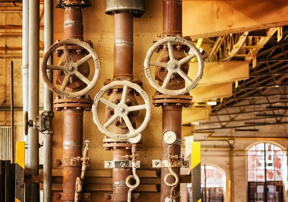
Plunger pumps place the high-pressure seal in a stationary gland while a smooth cylindrical plunger slides through it, allowing industrial plunger designs to operate from 70 bar up to 2,070 bar (1,000–30,000 psi) [S3].
Piston pumps carry the seal on the moving piston inside a fitted cylinder, which limits the practical pressure ceiling but improves volumetric efficiency and gas-handling in low-to-medium pressure process service [S1][S4].
Definition and Operating Envelope
Both machines are positive-displacement reciprocating pumps driven by crank, steam, hydraulic, pneumatic, or electric power, and flow equals plunger or piston area multiplied by stroke length times the number of working chambers times the drive speed [S3].
Because the seal is stationary on a plunger pump, the only moving wetted part is the rod itself, and the seal can be repacked without draining the fluid chamber on most designs [S1]. On a piston pump, the seal is bonded to the piston, so the entire bore of the cylinder becomes a wearing surface that must be machined to a tight clearance to the piston diameter [S1][S2].
The operating envelope separates sharply on pressure: industrial plunger pumps cover roughly 70–2,070 bar (1,000–30,000 psi) per the published literature, while piston pumps are generally used at lower pressures and higher speeds where the moving-seal friction stays manageable [S3].
Selection Criteria: Pressure, Fluid, and Maintenance Access
Plunger pumps win on three measurable criteria: peak discharge pressure, mean time between seal repacks, and tolerance of dirty or abrasive fluids, because the gland seal and the plunger can be specified as separate wear items [S1].
Piston pumps win on three other criteria: tighter running clearances (the piston fits tightly inside the cylinder, the plunger fits loosely), better suction lift, and lower cost at pressures below roughly 100 bar where the seal-friction penalty is small [S2][S5].
Materials follow from the duty: general-service and oil-service plunger pumps typically pair an iron cylinder with an iron plunger, while continuous-duty water and oil applications may specify solid ceramic plungers for wear life, with the caveat that ceramic is poor in acidic media [S3].
Common wetted materials across both types include bronze, brass, steel, stainless steel, iron, and nickel alloys; ceramic is the hardest available plunger material, with high compressive strength but low tensile strength that limits geometry to simple cylinders [S1][S3].
Comparison: Plunger vs Piston on Four Decision Criteria
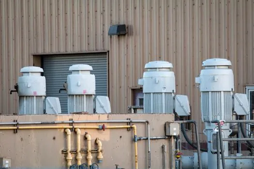
On maximum discharge pressure, the plunger pump reaches the published 2,070 bar (30,000 psi) ceiling, while the piston pump is generally capped well below that by seal friction and heat [S1][S3].
On seal life and maintenance, the plunger pump has a static gland that can be repacked in place and isolates wear to the rod, while the piston pump requires pulling the piston and the bonded seal from the cylinder for service [S1].
On fluid compatibility, the plunger pump is forgiving of particulates and is widely used for municipal and industrial sewage, and for oilfield water, polymer, and chemical injection, while the piston pump is preferred for clean, low-viscosity liquids and for moderate-viscosity oils [S3][S5].
On cost and footprint, the piston pump is typically cheaper and smaller at pressures below roughly 100 bar; the plunger pump costs more but delivers substantially higher pressure per unit displacement, which lowers the number of stages required for a given duty [S3][S5].
Use Cases by Industry
Plunger pumps dominate high-pressure water jetting, oilfield water and polymer injection, chemical injection, cementing, BOP testing, and steel dephosphorization, all of which routinely exceed 350 bar and often push past 700 bar [S3][S5].
Piston pumps dominate boiler feed, light oil transfer, lube-oil service, and metering applications where tighter bore-to-piston clearance improves volumetric efficiency and the duty pressure stays below roughly 100 bar [S4][S5].
For reciprocating-pump selection rules across drilling and well-service skids, the engineering decision tree in this pump category guide and the wider reciprocating pump principles page map the same seal-placement logic onto industrial skids.
Failure Modes and Operating Limits
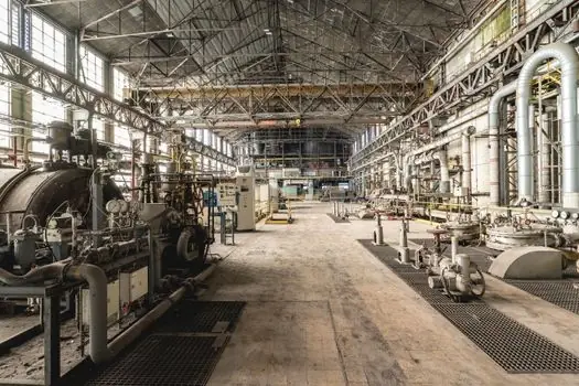
The dominant failure mode on a piston pump is seal and cylinder-bore wear, because the bonded seal slides against the bore on every stroke, and the resulting friction both limits maximum pressure and accelerates surface fatigue [S1].
The dominant failure mode on a plunger pump is packing wear at the gland and surface scoring on the plunger rod, and because the seal is stationary, plunger failure rarely causes the catastrophic loss of compression seen on a worn piston seal [S1][S3].
Plunger pumps also handle liquids with entrained gas more poorly than piston pumps, since the loose plunger fit lets gas bypass back to suction; operators usually specify a flooded suction or a pulsation dampener to keep volumetric efficiency above roughly 90% [S2][S4].
For comparison with other positive-displacement technologies, the diaphragm pump reference covers the leak-free variant used on chemical injection where neither plunger nor piston wetted parts can be exposed to the process.
Standards and Sourcing Notes
Hydraulic Institute standards and API 674 cover positive-displacement reciprocating pumps including both plunger and piston designs, and the published pressure envelope of 70–2,070 bar (1,000–30,000 psi) for plunger pumps is consistent with manufacturer datasheets for triplex and quintuplex oilfield units [S3][S5].
For related selection logic on reciprocating pumps, the piston vs plunger high-pressure guide walks through triplex and quintuplex configurations, and the plunger pump operating envelope maps pressure, stroke speed, and fluid type against NPSH margins.