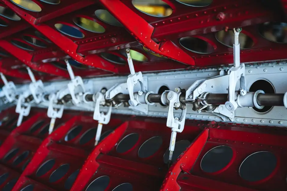
A rack and pinion pneumatic actuator produces quarter-turn rotary output by driving two opposing linear racks against a single centered pinion gear, with the dual-rack geometry providing the force balance that single-piston designs cannot match [S1][S4].
The mechanism is built around three load-bearing parts: two opposed pistons with machined teeth (the racks) and a single shaft-mounted gear (the pinion) that couples directly to the valve stem [S4]. Internal cross-section drawings consistently show symmetrical cylinder bores, a center body cavity for the pinion, and identical end caps that allow the same housing to be used for double-acting and spring-return configurations [S8].
Cross-Section Architecture: Symmetric Bores, Centered Pinion, and Modular End Caps
The internal cross section of a typical rack and pinion actuator shows two mirror-image cylinder bores flanking a central pinion cavity, with the pinion shaft passing through the body wall via O-ring sealed bearings to the external drive bushing [S3][S8]. The piston racks ride on the honed inner surface of the bores; the bore surface finish and the rack-to-pinion gear mesh together define positioning accuracy and cycle life [S8]. Hard-anodized extruded aluminum is the dominant body material, paired with honed internal surfaces to reduce seal friction and extend service intervals [S8].
The pinion itself is the only rotating element exiting the body, and it is typically sized to ISO 5211 mounting patterns for direct bolt-on to ball, butterfly, and plug valves [S2]. NAMUR accessory-mounting dimensions on the pneumatic port and the top accessory face allow solenoids, positioners, and limit switches to bolt on without adapter plates [S2]. This standardized interface is why a single actuator body can be reconfigured by changing the end-cap stack from double-acting to spring-return without altering the center section [S8].
How the Mechanism Converts Air Pressure to Rotary Stroke
Supply air admitted to one end cap pushes its piston inward, the rack teeth drive the pinion through approximately 90 to 100 degrees of rotation, and exhausting the opposite end cap lets the second piston follow [S2][S7]. The two racks moving in opposite directions apply equal and opposite tangential force on the pinion, which keeps side load on the shaft bearings near zero and lets the unit run for high cycle counts on quarter-turn duty [S1].
Reversing the rotation is done by redirecting the supply to the opposite port (direct-acting mode) or by letting a compressed spring stack in one end cap drive the return stroke (spring-return mode) [S2]. Because the same center body and end-cap pattern are shared, plants can stock one body SKU and switch fail-safe behavior by swapping the spring cartridge, rather than holding two separate actuator models [S8].
Internal Components Worth Specifying
Inside the housing, the parts that drive service life are the piston seals, the pinion shaft seals, the bearing arrangement, and the spring pack (for spring-return units), all of which are field-serviceable in most modular designs [S2][S3]. Hard-anodized aluminum bodies with PTFE or NBR piston seals are the baseline for general-purpose service, while coated bodies and stainless fasteners are common for corrosive or coastal installations [S5][S8].
Patent literature on the geometry shows that the rack teeth are typically machined directly into the piston body, which removes a wear interface and lets the assembly tolerate the side forces that appear at end of stroke [S3]. Most units also include travel stops on the end caps, adjustable in the field, so the open and closed positions can be trimmed by 5 to 10 degrees without disassembling the gear train [S2]. For a broader look at how the actuator packages with its valve and positioner, the encyclopedia entry on pneumatic valve actuators covers the system-level interfaces.
Rack and Pinion vs Vane vs Scotch Yoke: A Decision Comparison
For quarter-turn service, the three competing pneumatic architectures are rack and pinion, vane, and scotch yoke, and they trade off part count, torque profile, and cycle life in ways the spec sheet alone does not make obvious [S4][S6]. On a four-criterion basis, rack and pinion sits in the middle on part count, delivers nearly constant torque through the stroke, accepts both spring-return and double-acting in the same body, and is rated for high cycle duty with predictable backlash.
Vane actuators use a single moving part and offer a more compact envelope, but the torque output is concentrated near the start of stroke and drops as the vane rotates, which limits their use on high-breakaway valves [S4]. Scotch yoke designs convert piston force through a sliding yoke and produce a strong torque peak at 0 and 90 degrees, which suits high-torque butterfly and ball service but ties the unit to a fixed travel angle and a heavier frame [S6]. Where the application is general-purpose quarter-turn isolation with a need for either fail-safe or double-acting flexibility in the same footprint, rack and pinion is the default pick [S5][S8].
Operating Envelope, Mounting Interfaces, and Common Failure Modes
Standard units are rated for clean dry air at 80 to 120 psi (roughly 5.5 to 8 bar) supply, with aluminum-body designs running from approximately -20 to 80 degrees C in general service and higher with seal upgrades [S5][S8]. Output torque scales with piston area, supply pressure, and the rack/pinion pitch, so doubling the bore area or the supply pressure roughly doubles the available torque at any point in the stroke [S6]. Mounting follows ISO 5211 for the valve interface and NAMUR for accessories, which means a positioner or switch box from any major brand bolts on with no adapter plate [S2].
The dominant failure modes are seal wear on the piston and pinion shaft, spring set in spring-return cartridges, and corrosion of the body in salt or chemical atmospheres; all three are addressable through preventive seal and spring replacement rather than full unit replacement [S5]. For plants that already standardize on a related pneumatic component family, the pneumatic actuator reference covers the wider portfolio and how rack and pinion fits alongside it. Where the actuator is driving an isolation valve in a process line, the instrumentation side (positioners, I/P converters, limit switches) is covered in the checking and testing apparatus encyclopedia entry.
Specifying a Rack and Pinion Actuator: Inputs That Actually Matter
The four inputs that drive a correct sizing are the valve breakaway torque at the worst-case differential pressure, the required safety factor (commonly 1.25 to 1.5 for modulating and 1.5 to 2.0 for isolation), the supply pressure available at the actuator, and the fail-safe mode (spring-return closed, spring-return open, or double-acting) [S6]. With those four locked in, the bore size, the pinion pitch, and the spring stack are selected, and the body length adjusts to fit the required torque without changing the mounting pattern [S2][S8].
Travel is typically factory-set to 90 degrees with field adjustment of plus or minus 5 to 10 degrees on each end stop, and the pinion is keyed to the valve stem to ISO 5211 so the same actuator can be bolted to a ball, butterfly, or plug valve without modification [S2][S8]. For applications where the valve is the storage interface rather than the process interface, the pallet rack and storage rack encyclopedia entries cover the parallel mechanical-design decisions on the materials-handling side.
Selection Cues and What to Verify Before Purchase
Rack and pinion is the right call when the application is general quarter-turn service, when the same body needs to be reconfigurable between double-acting and spring-return, when the plant standardizes on ISO 5211 and NAMUR accessories, and when high cycle life with predictable backlash matters more than a slightly smaller envelope [S5][S8]. It is the wrong call when the valve has a very high breakaway torque at 0 or 90 degrees (where a scotch yoke peaks better), when the cleanest possible internal volume is required (where a vane has fewer leak paths), or when the supply media is hydraulic oil at high pressure, which pushes the design toward a dedicated hydraulic actuator rather than a pneumatic unit [S4][S6].
Before signing a purchase order, verify the body material and coating against the chemical exposure, confirm the temperature range of the piston seals, check the cycle-life rating at the actual supply pressure rather than the maximum, and confirm that the ISO 5211 mounting pattern on the actuator matches the valve stem and the NAMUR pattern on the top matches the planned positioner or switch box [S2][S5][S8]. For related actuator-driven equipment decisions, the steel cross-section data in steel section is useful when the actuator is mounted on a heavy carbon-steel valve body.
Trackable signals to watch through the rest of 2026: published cycle-life data at supply pressures below 80 psi (5.5 bar) from the major rack and pinion OEMs, and any revisions to the ISO 5211 and NAMUR accessory interface drawings that govern the bolt patterns these units ship with. Also worth following: corrosion-coating qualification data for aluminum-body units in coastal and chemical-service plants, since that is the single biggest driver of mid-life body replacement in field service.
Related analysis: Grey Cast Iron Price Hikes Track Scrap Steel, Energy, and Freight, Not Hot-Rolled Coil.