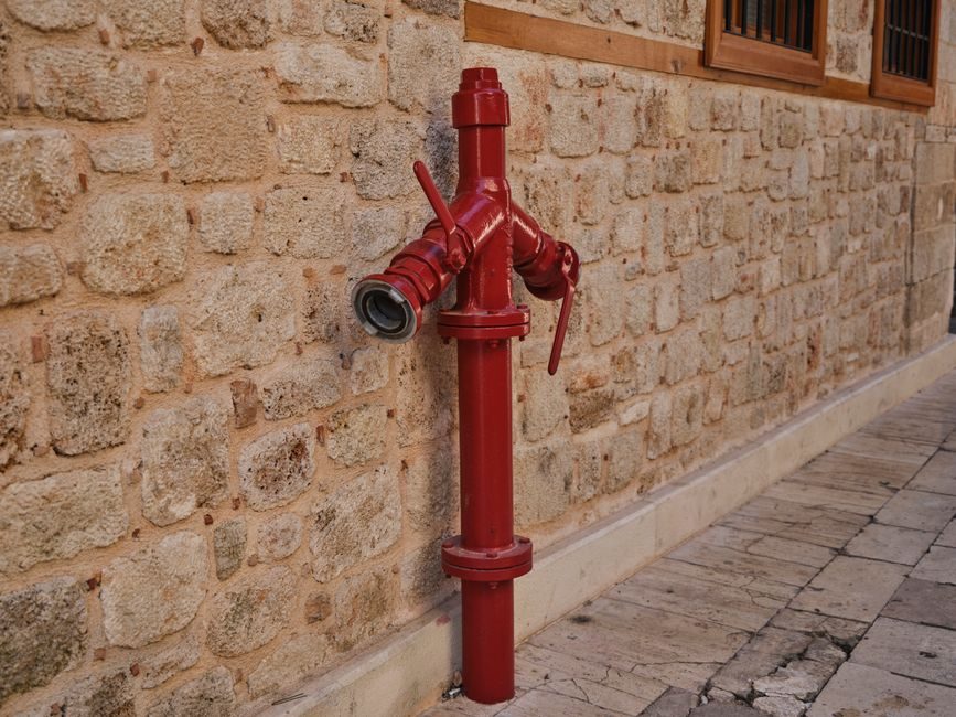
Pneumatic tubing and FRL (Filter-Regulator-Lubricator) units serve adjacent, non-interchangeable roles in a compressed-air circuit: tubing is the conveyance medium, the FRL is the air-conditioning station that sits upstream of it [S1][S2].
Specifying the wrong pairing — for example, a polyamide tube on a high-pulse cylinder loop without a sufficiently large receiver and regulator — is the single most common root cause of premature seal and hose failure in shop-floor pneumatics [S1].
Definition and Functional Boundary
Compressed-air systems move energy from a compressor to a pneumatic actuator through two distinct physical assemblies: a treatment block and a distribution network. The FRL unit is the treatment block — it removes particulate and entrained water, steps the pressure down to a working setpoint, and (in lubricator-equipped configurations) injects a metered oil mist into the airstream [S2]. The tubing is the distribution network — it routes that conditioned air from the FRL outlet port to valves, cylinders, and tools [S1].
Tubing is therefore downstream of the FRL, never upstream of the filter stage. Air that has not passed through a coalescing or particulate filter will carry compressor oil, rust scale and condensed water into the tube ID; over time that contamination scours the tube wall, degrades O-rings in push-in fittings, and fouls solenoid valve spools [S2].
Material Bands and Operating Limits
Four polymer families dominate the pneumatic-tube market, and each maps to a different operating envelope [S1][S3]:
Polyamide (PA / Nylon 6, Nylon 12) — the most-specified general-purpose option. Operating window typically -40 °C to +80 °C, with maximum working pressure in the 20–30 bar band for 6 mm and 8 mm OD at 25 °C; pressure derates with rising temperature, falling to roughly 50% of the 25 °C rating at +80 °C [S1][S3]. PA12 absorbs less moisture than PA6 and is the preferred choice for humid or washdown environments.
Polyurethane (PU) — flexible, kink-resistant, supplied in metric and inch coils. Maximum working pressure is lower than PA, typically 8–10 bar at 25 °C for 6 mm and 8 mm OD, and the temperature window is narrower (-20 °C to +60 °C). PU is the default pick for robot dress packs, tool balancers and any moving-arm routing where flex life is the dominant constraint [S1].
Polyethylene (PE) and PTFE (PTFE) round out the catalogue. PE is the low-cost option for low-pressure cabinet air (commonly ≤10 bar) and inert gas distribution; PTFE covers the high-temperature and chemically aggressive niches (-60 °C to +260 °C band) where PA and PU degrade, and is common in laboratory, semiconductor and pharmaceutical skids [S1].
FRL Spec Criteria and Sizing Logic
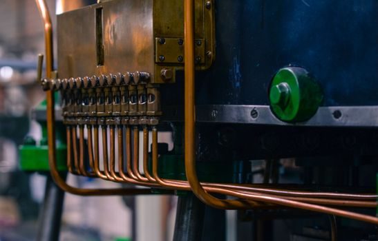
The FRL unit is selected on three numeric axes: port size, flow capacity, and pressure rating [S2]. Port size is the most-overlooked knob — undersizing the FRL port relative to the downstream tubing and cylinder ports introduces a choked-flow restriction that defeats the regulator's ability to hold setpoint under transient demand.
Common industrial port sizes are G1/8, G1/4, G3/8, G1/2, G3/4 and G1 (BSPP), with NPT versions for North American builds; matching the FRL port to the tube OD and the pneumatic tubing fitting thread avoids adapters that add leak joints [S2]. Flow capacity is published as Cv (US) or kv (metric, m³/h at 1 bar ΔP); a G1/4 FRL typically delivers around Cv 1.0–1.5, while a G1/2 unit lands in the Cv 4–6 band [S2].
Pressure-rating tiers follow the same partition as tubing: standard industrial FRLs cover 0.5–10 bar regulated output with 16–20 bar maximum inlet; high-pressure variants rated to 30–40 bar inlet serve hydraulic-pneumatic hybrid skids and PET-blow applications [S2].
Decision Matrix: Pairing the Two Assemblies
The matrix below lines the four common tubing materials against the most-cited selection criteria for an FRL-fronted distribution line. Use it as a single-pass filter before opening a vendor catalogue. [S1]
PA (Nylon 12): cost band — low to moderate; temperature — -40 °C to +80 °C; pressure ceiling — 20–30 bar at 25 °C; chemical resistance — good against oils and weak acids, poor against strong acids and chlorinated solvents; best fit — general factory air mains, fixed routing, cylinder feeds where rigidity and creep resistance matter [S1][S3].
PU: cost band — moderate; temperature — -20 °C to +60 °C; pressure ceiling — 8–10 bar at 25 °C; chemical resistance — moderate, attacked by concentrated acids and certain solvents; best fit — moving-machine routing, tool arms, robot dress packs, short flexible jumpers [S1].
PE: cost band — lowest; temperature — -20 °C to +60 °C; pressure ceiling — typically ≤10 bar; chemical resistance — good against many dilute chemicals; best fit — inert-gas lines, cabinet purge, low-pressure instrument air [S1].
PTFE: cost band — highest; temperature — -60 °C to +260 °C; pressure ceiling — typically 10–20 bar at 25 °C; chemical resistance — best-in-class against nearly all industrial chemicals; best fit — pharma, semiconductor, laboratory, aggressive-chemical skids [S1].
Compatibility and Integration Rules
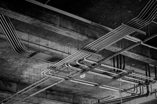
Push-in (cartridge) fittings dominate the assembly side, and the tube-to-fitting interface is the leak-path most often mis-specified. PA and PU tubes both accept standard push-in connectors, but the grip-ring geometry differs — a fitting rated for PA may not hold PU under vibration, and vice versa [S3]. Specifying one connector family across mixed tube stock is the cheapest way to standardize a build.
For high-vibration or high-pulse service (cylinder reciprocation faster than roughly 60 cycles/min, or pressure transients above the working pressure), the FRL must sit within roughly 2 m of the actuator, the tube runs must be clamped at ≤0.5 m intervals, and the tube OD should be stepped up (6 mm → 8 mm or 10 mm) to reduce ΔP and surge velocity [S1][S2].
When a hydraulic power unit is also present on the same skid, the pneumatic and hydraulic circuits must be physically separated: shared troughs invite cross-contamination of the FRL filter element with hydraulic oil, which collapses the filter's water-removal efficiency within hours of commissioning [S1].
Limitations, Failure Modes and Standards
Tubing failure modes split into three families: burst (over-pressure, usually from a failed regulator or kinked line), fatigue (pulse cycling at small bend radii, usually at the fitting crimp), and chemical attack (wrong polymer for the media) [S1]. FRL failure modes are concentrated in the regulator seat and the filter element: a regulator that has been cycled through its full pressure range without downstream demand will chatter and erode the seat, while a filter element left in service past its ΔP trigger will begin to migrate captured oil downstream.
For hazardous-area builds, FRL bodies and solenoid valves must carry the ATEX / IECEx marking that matches the zone (for example, ATEX category 2 for Zone 1, category 3 for Zone 2), and the certification dossier should be requested at the quotation stage rather than after delivery [S1][S2]. Tubing itself is generally a passive component and does not require ATEX certification, but metallic (stainless) compression fittings and antistatic PU compounds may be mandated on Zone 0 and Zone 1 builds depending on the notified-body interpretation.
Quality benchmarks to anchor a purchase spec: ISO 8573-1 for compressed-air purity class (the typical factory target is 7:4:2 or better, meaning ≤10 mg/m³ solid, ≤5 mg/m³ water, ≤1 mg/m³ oil), and ISO 14743 for push-in pneumatic fittings geometry [S1][S2].
2026 Sourcing and Supply Signals
Asian — and in particular Chinese — pneumatic-component manufacturers have become the dominant global supply source for both FRL units and push-in tubing, with multi-country distributor networks covering 30+ markets and ISO 9001 manufacturing certification as a baseline [S3]. This is consistent with the broader pattern in compressed-air equipment, where Chinese output leads the global air compressor production capacity map and where the same domestic hubs feed both compressor OEMs and downstream component makers.
For buyers comparing tubing lead times in mid-2026: PA and PU stock sizes (6 mm, 8 mm, 10 mm, 12 mm OD) are widely available ex-warehouse from Chinese and Taiwanese factories with quoted lead times in the 2–4 week band, while PTFE and high-purity PU compounds carry 6–10 week lead times and minimum-order-quantum conditions [S1][S3]. FRL units configured to non-standard port threads or with integrated soft-start/dump-valve functions are the lead-time drivers on the treatment side, with non-stock builds running 8–12 weeks from order to ex-works.
Buyers should track two signals over the next two quarters: first, ISO 8573-1 compliance certificates per shipment, since air-purity class drift is the leading indicator of FRL filter-element counterfeit risk; second, the resin-spot price for PA12 and PTFE, which sets the tubing cost band roughly one quarter ahead of finished-goods pricing [S3].