PTFE thread-sealant tape is supplied in three density bands — 3.0–3.4 mil (0.5–0.7 g/cm³) standard, 3.4–3.8 mil (0.8–1.1 g/cm³) high density, and 3.6–4.2 mil (1.1–1.6 g/cm³) premium — and the grade must be matched to the service fluid, thread pitch, and operating pressure before the first wrap is applied [S2].
This guide consolidates the three work domains where field engineers actually handle PTFE on site: male-thread sealing tape, flexible hose-end assembly, and PTFE-lined steel piping. Each domain uses a different failure mechanism and a different acceptance test, and the symptoms look identical at the joint — drip, weep, or pressure decay — so the workups diverge from the first step.
Thread Sealant Tape: Grade Selection and Wrap Technique
Standard-density tape at 3.0–3.4 mil is reserved for non-critical residential water and air joints; high-density tape at 3.4–3.8 mil covers most process-plant pipe threads and is colour-coded by application (yellow for gas, red for high-temperature, green for oxygen-service variants) [S2]. Premium 3.6–4.2 mil tape at 1.1–1.6 g/cm³ is specified for natural gas, oxygen, and large coarse threads where cold flow and vibration are the dominant failure drivers.
Wrap direction matters: tape is wrapped clockwise onto male threads (the same direction as thread engagement) so the fitting make-up tightens onto the tape rather than unwinding it. The number of wraps scales with thread size — typically 2–3 wraps on 1/4″ NPT rising to 6–8 wraps on 1″ and above — and the first thread must stay clean of tape to avoid media contamination [S2]. Coverage of the engaged thread length, not the shoulder, is the visual acceptance check before make-up torque is applied.
PTFE Hose End Assembly: Tooling, Fittings, and Torque Bands
PTFE hose-end work is dominated by four fitting families — reusable, crimp, compression, and flare — and the choice locks in both the tooling list and the torque target. Reusable fittings allow multiple rebuilds on stainless- or nylon-braided PTFE hose; crimp fittings deliver a permanent swaged connection rated for the highest working pressures in the catalogue; compression and flare fittings use thread or mechanical flare to seal and are typical on instrumentation and chemical-skid work [S3][S4].
The required tooling list is identical regardless of fitting style: a sharp hose cutter for square, burr-free ends; vice jaws to anchor the hose; a deburring tool to clear the inner liner; a torque wrench to land the nut at manufacturer-specified value; and a pressure-test kit to verify the assembly before service. A clean, square cut is the single most common cause of post-install leak — ovalised or frayed ends produce a gap that no amount of torque will seal, and re-cutting the hose end is the only corrective action [S3].
Make-up torque must come from the fitting manufacturer's published table, not field feel. Under-torque produces a slow weep on first pressure rise; over-torque distorts the PTFE liner and produces a delayed leak that returns even after re-torque. The acceptance test is a hold at 1.5× working pressure (or per the hose manufacturer's proof value) for the soak time stated on the data sheet, with zero visible leak and zero pressure decay as the pass criterion [S3].
PTFE-Lined Steel Pipe: Flange Management and Bolt-Up Pattern
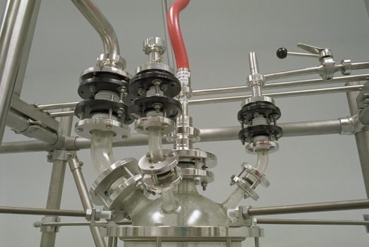
PTFE-lined pipe failure is almost always traced back to bolt-up, not liner chemistry. The work sequence is: inspect the liner face for cracks or score marks; confirm the gasket is a full-face PTFE or modified-PTFE type matched to the flange class; hand-locate the gasket dry; then torque bolts in a cross pattern — opposite pairs, in three to four incremental passes — to the value stamped on the data plate [S6].
Over-torque crushes the PTFE liner past its elastic limit and the joint leaks on the first thermal cycle; under-torque leaves a gap that relaxes further on heat-up. Welding adjacent to a PTFE-lined spool is a hard prohibition: the heat-affected zone degrades the liner's chemical resistance and produces a delayed failure that is invisible from outside the pipe. The acceptance test is a hydrostatic hold at the line test pressure, with a final pass/fail recorded against the gasket manufacturer's leak-rate class [S6].
Field engineers also use lined-pipe work as a crossover with adjacent elastomer-lined systems: the industrial rubber installation reference covers cure windows and Shore-A acceptance bands that are conceptually similar, even though PTFE does not cure and uses a different torque-pass schedule.
Failure Modes and When to Replace, Not Re-Work
Three failure modes end the re-work conversation. On threaded joints, a persistent drip after two full re-torques signals a damaged thread or stretched female fitting, and the spool section must be replaced. On hose assemblies, any liner extrusion visible at the fitting ferrule — a tell-tale white "ribbon" of PTFE — means the hose has been over-pressurised and must be scrapped, not re-cut. On lined pipe, any cold-flow line, hairline crack, or blister on the liner face is a reject: spot-repairing PTFE in the field is not a recognised practice [S2][S3][S6].
The escalation path is identical across all three domains: isolate, depressurise, drain, then replace the affected component. For instrumentation and chemical-service PTFE hose skids, the maintenance workflow is often tied into the same planner that drives protocol gateway diagnostics, so a logged pressure-decay event on a PTFE hose should trigger the same work-order template as a valve-pass-rate alert.
Tools, Acceptance Tests, and Common Pitfalls
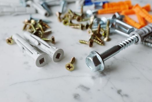
Tooling can be condensed into a single field kit: PTFE tape in three density grades, sharp hose cutter, deburring tool, calibrated torque wrench, cross-pattern marker for flange bolts, hydrostatic test pump with chart recorder or digital logger, and a 10× magnifier for liner inspection. Anything missing from that list typically shows up as a leak on the commissioning punch-list. [S2]
Acceptance values cluster around three reference points: thread-seal tape wrap count by pipe size, hose proof pressure at 1.5× working pressure with zero decay over the stated soak, and lined-pipe hydrostatic hold at line test pressure with leak rate per gasket class. Field engineers building out a new install spec will often cross-reference the hose-end pressure bands against slurry pump duty cycles, because the same elastomer/PFTE wear mechanism drives both liner life and total cost of ownership.
Track these two signals on the next service interval: (1) the ratio of leak-call returns to total PTFE joints installed on the unit — a baseline above 2% in the first 90 days points to grade mis-selection or torque-wrench calibration drift; (2) the count of liner-face rejects during routine inspection — any non-zero value in a stable line is grounds to audit the bolt-up sequence and the gasket inventory.
Spec-level background on the components involved: linear guide.