Polyurethane half shell pipe insulation is the preformed factory-split rigid foam section most engineers reach for first on chilled water, district cooling, and cold-process lines, because it pairs one of the lowest published thermal conductivities in the foam family with a closed-cell structure that resists water vapor absorption and dimensional change. Typical k-values cited for PUF pipe sections sit at an initial 0.021 W/m·K at 100°C mean, with a service envelope commonly published as -180°C to +110°C [S5].
The half shell format solves a jobsite problem: long straight chilled water mains in mechanical rooms, plant tunnels, and ceiling service corridors cannot be slipped over a pipe end. A factory-cut shell with a longitudinal slit drops over the pipe, closes along the seam, and is then sealed with a compatible vapor tape or mastic to restore the continuous vapor envelope. Standard factory lengths are 1 m, and standard thicknesses span 25–100 mm to match the condensation-control thickness calculated from ambient temperature and relative humidity [S5][S6].
What a Polyurethane Half Shell Actually Is
A polyurethane half shell is a rigid, closed-cell thermoset foam section molded or cut from a bun of rigid PU (or PIR) foam and split along the pipe axis so it can be clamped around an in-service line. Density for chilled-water service is published at 36±2 kg/m³ for the baseline PUF pipe section, with higher densities supplied on request where compressive load is the driver [S5]. Closed-cell rigid PU is the same family that ships as polyurethane insulation for LNG, district heating, and chemical plant lines, distinguished from flexible polyurethane elastomer foam by its rigidity and load-bearing capacity.
PU half shells are sold to fit standard pipe NB sizes, with one Philippine-tier supplier publishing 50 to 250 mm NB coverage as stock and casting other diameters to order [S5]. Available wall thicknesses of 25, 40, 50, 75, and 100 mm cover the bulk of condensation-control and energy-loss calculations on 4°C–13°C chilled water. Factory longitudinal length is typically 1 m, so the installer is buying a series of seams, not a continuous wrap, which is why the seam-sealing discipline drives real-world performance.
Why Half Shells, Not Spray or Roll
On chilled water the engineer is balancing three jobs at once: thermal resistance, vapor control, and surface protection. Rigid PU half shells hit all three because the closed-cell structure absorbs very little water and the factory skin (or applied foil/kraft facing) is already a vapor retarder, whereas open-cell spray foam and fiberglass batts require a separate vapor barrier to avoid condensation wetting the cold pipe [S1][S4].
Compare the working envelope against the other four common chilled-water insulation families, each tied to a published attribute from the research set:
PU rigid half shell: k ≈ 0.021 W/m·K initial, closed-cell, vapor-tight with foil/kraft, -180°C to +110°C service, density 36±2 kg/m³, low maintenance [S5].
Phenolic foam (e.g. Polyguard PolyPhen®): closed-cell, very low k, permeability approaching 0.0 perm when paired with a quality vapor barrier, recommended by the manufacturer for chilled water lines where fire and smoke are dominant spec drivers [S1].
Elastomeric (nitrile rubber): flexible closed-cell, favored for refrigeration lines and small-bore AC piping where vibration and frequent re-work are routine, no separate vapor barrier needed [S4].
Cellular glass: zero-permeability, non-combustible, high compressive strength, tolerant of wide temperature swings, heavier and more expensive per R-value [S1].
Fiberglass: cost-effective open-cell, requires a separate vapor barrier to keep moisture out of the cold pipe jacket, suited to above-ceiling runs where fire rating dominates [S1][S4].
Chilled Water Service: Condensation, Heat Gain, Freeze

Chilled water supply is normally pushed out at about 7°C and returned at roughly 13°C, with the chiller resupplying the loop with refrigerant-cooled water at about 7°C or less, which is the surface temperature that drives condensation risk on any uninsulated or under-insulated section [S1]. The chilled water pipe insulation job list is published and specific: stop surface condensation that otherwise feeds mold growth and corrodes the system, limit parasitic heat gain so the chiller does not have to re-cool water that has warmed in the pipe, and prevent freeze-up in unheated mechanical rooms or below-grade service [S1].
NAIMA's CI-228 guide frames insulation selection as a recommended method, not a code, and lists the same design inputs: pipe size, fluid temperature, ambient temperature and relative humidity, and the chosen facing or vapor retarder that keeps the closed-cell foam dry over the life of the system [S6]. The North American Insulation Manufacturers Association document is widely cited because it ties those inputs to a published table of insulation thickness by pipe size and operating temperature, which is the same thickness table a PU half shell spec sheet eventually maps onto.
Specifying a PU Half Shell: Density, Thickness, Facing, Joint
Lock the spec to four data points and the buying decision becomes mechanical. Density at 36±2 kg/m³ is the published baseline for chilled-water service, with higher densities specified only where the shell is also acting as a mechanical spacer or load-bearing saddle [S5]. Insulation thickness affects both energy efficiency and condensation control on chilled water piping, and the recommended thickness per pipe size should be taken from the NAIMA guide or an equivalent ASHRAE calculation [S6].
Facing is the second decision. Standard kraft paper is fine for dry, conditioned mechanical rooms; aluminum foil is the right answer where ambient RH is elevated or where the line passes through a humid plenum, because foil is a Class 1 vapor retarder and is the published stock facing for PUF pipe sections [S5]. Joint sealing is the third: longitudinal seam and circumferential butt joints must be sealed with a foil-scrim-kraft or all-service jacket tape matched to the facing, because the factory vapor envelope is only as good as the seams the installer closes. The fourth point is the operating envelope. If any portion of the line sees temperatures above the published 110°C ceiling of standard PUF, escalate to PIR (polyisocyanurate) or a higher-temperature phenolic rather than asking PU to do a job outside its data sheet [S4][S5].
Where Half Shells Are the Wrong Choice

Do not specify PU half shells where the line is exposed to hydrocarbons, where it is regularly wetted, where the fire-rating spec is the dominant driver, or where the line is so short and convoluted that the seam count overwhelms any labor saving. Hydrocarbon exposure attacks the closed-cell structure; the published spec for rigid PUF does not list oil and solvent resistance as a feature, and the manufacturer is silent on chemical compatibility, so elastomeric nitrile or cellular glass is the safer pick for oil-contaminated service [S2][S4].
For high-temperature process lines above the PU 110°C ceiling, PIR (polyisocyanurate) is the upgraded choice, with published continuous exposure tolerance up to 300°F (about 149°C) without rapid degradation, and mineral wool is the right call for the same envelope up to roughly 1,000°F (about 538°C) [S4]. For below-grade chilled water in a wet soil envelope, foamglass (cellular glass) wins because its zero-permeability body is unaffected by groundwater, where any organic foam can eventually wick at the seams unless the jacket is perfect [S1].
Cross-Reference: Material vs Decision Criterion
Line the four major options up against the four decision criteria an engineer actually weighs on a chilled-water job. Thermal performance: PU rigid foam leads on k-value per millimeter, with phenolic close behind; elastomeric is competitive on small-bore; fiberglass and mineral wool trail. Vapor control: cellular glass and phenolic-with-barrier are essentially zero-perm; closed-cell PU with foil facing is also effectively vapor-tight; elastomeric is self-barrier; fiberglass needs a separate jacket. [S5]
Fire and smoke: mineral wool and cellular glass are non-combustible; phenolic is published as low smoke; elastomeric and PU need to be checked against the project's ASTM E84 or local equivalent, because standard PU is not a fire-rated foam by default. Mechanical robustness: cellular glass and high-density PU win on compressive load; elastomeric wins on vibration and rework; phenolic is rigid but more brittle in handling. The published takeaway from the manufacturer is that "retains its shape and insulation effectiveness across a wide range of temperatures" is the PU foam's headline advantage for chilled water, which is exactly why it keeps its place on the chilled-water portion of the spec where temperatures stay in the 0°C to 15°C band [S4].
Installation Discipline That Drives Real Performance
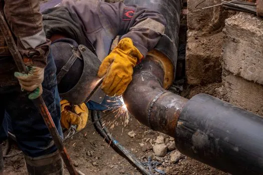
Factory k-value is a marketing number until the seam is sealed, the valve and fitting covers are foamed in place, and the vapor jacket is continuous through hangers and penetrations. A published spec for industrial PU systems such as URTECH emphasizes that the foam "prevents the harmful effects of freezing and keeps the chilled water at a constant temperature," but only when the system is applied as a continuous envelope, including elbows, tees, and end caps, which is the same envelope discipline NAIMA's guide and the half-shell makers all reference [S3][S6].
For the polyurethane half shell specifically, the published scope is district heating and cooling, oil and gas, industrial process, and cryogenic applications, with the half shell form factor selected for any run that is too long or too large in diameter to be wrapped with a continuous roll [S2]. Use the 1 m factory length to plan the seam pattern, pre-cut all butt-joint miters at the shop, and seal every joint with facing-matched tape. The two failure modes that show up on PU chilled-water jobs are seam wetting (which degrades k and corrodes the pipe) and facing delamination at hangers, both of which are caught by a basic inspection at the 10% and 100% install milestones.
Sourcing and Standards Touchpoints
Two reference documents are worth pinning to a submittal package. The NAIMA guide to insulating chilled water piping (CI-228) is the published recommended method for thickness selection, facing selection, and insulation protection on commercial and institutional chilled water, and is the right baseline for any NA-based spec [S6]. For materials selection across the broader pipe-insulation family, manufacturer comparison pieces such as the Polyguard chilled-water guide and the Buckaroos 9-types breakdown line PU up against phenolic, elastomeric, fiberglass, mineral wool, polyisocyanurate, polystyrene, and polyethylene with the same kind of operating-envelope and application language that should show up in the spec narrative [S1][S4].
Local fire and smoke ratings (ASTM E84 / UL 723, FM approval, NFPA 90A for plenum use) must be checked on the actual half shell being purchased, because published foam density and facing do not by themselves guarantee a project fire rating. For European and Middle East jobs, CE marking under EN 14308 (factory-made rigid PU and PIR pipe insulation) is the relevant harmonized standard, and the data sheet should carry the declared lambda, density, facing, and reaction-to-fire Euroclass.
For a broader read on how the polyurethane foam family is shifting its flame retardant chemistry in 2026, see the related coverage of polymeric FR substitution in EPS and XPS foam, which covers the same regulatory pressure that is now landing on rigid PU pipe insulation. The next spec to watch is the per-pipe-size NAIMA thickness table revision, and the second is any project-level push to swap standard PUF for PIR where the line sees a brief temperature excursion above 110°C, because PIR's published 300°F tolerance is the most common upgrade path off the standard PU data sheet [S4][S5].
The underlying component specifications are covered under ballast water treatment.