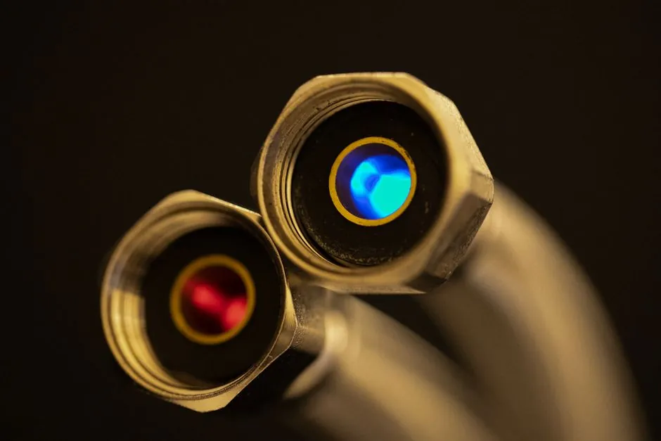
Push-in (push-to-connect, PTC) fittings seal by a collet gripping the outside diameter of a tube and an O-ring sealing the bore, so a square-cut tube end and full insertion to the depth mark are the only things standing between a working joint and a slow leak that bleeds compressed air for months [S2].
The same collet-and-O-ring principle is used across plastic (POM, PA66, brass with NBR) bodies in sizes from 4 mm to 12 mm OD, with stainless grab rings for repeated assembly [S2]. They are stocked for air, water, vacuum, and inert gas; tooling is limited to a sharp tube cutter, a depth-marking tool, and a marker, which is the entire reason compressed-air maintenance crews adopted them in the first place [S1][S2].
Tube prep and depth marking: the only step that decides whether the collet will actually grip
Cut the tube with a sharp wheel cutter so the cut is square within roughly 0.5 mm of perpendicular; an oval or angled cut lets the collet lobes ride over the tube under pressure instead of biting into it [S2]. For 1/4 in (6 mm OD) nylon or PU tubing the typical insertion depth is 17-19 mm, for 3/8 in (10 mm) about 21-23 mm, and for 1/2 in (12 mm) roughly 24-26 mm; the depth mark must be visible above the release sleeve after insertion so the installer can confirm full seat [S2].
Deburr the outside edge lightly with a deburring tool or the back of a cutter blade, and blow out any plastic or aluminium swarf with low-pressure air before pushing the tube home, because any chip across the O-ring will cut a leak path within the first 50 thermal cycles [S2]. For coiled tubing, let the coil rest straightened for a few minutes so the tube does not try to spring back out of the fitting after insertion [S2].
Insertion, pull test, and pressure ramp: the three checks that catch a bad joint
Push the tube in along the fitting axis in one smooth motion until resistance from the collet is felt, then continue until the tube bottoms on the internal stop, normally adding 1-2 mm of travel past the first tactile click [S2]. Once seated, grip the tube close to the body and tug axially with roughly 20-30 N of force for 4-12 mm fittings; any slippage means the collet has not engaged and the joint must be re-cut, never re-used by just pushing harder [S2].
Pressure ratings vary with body material and tube: POM plastic push-in fittings are typically rated to about 10 bar at 20 degrees C on 8 mm PU tubing, brass-bodied PTC fittings to 16-20 bar on the same tube, and stainless variants to 20-30 bar, with all ratings derated as temperature climbs past 40 degrees C [S2]. Always ramp from 0 to working pressure in at least 3 stages (25%, 60%, 100%) and hold each step for 30-60 seconds so any O-ring creep or tube shift shows up before the line goes into service [S2]. For shops standardising on compressed-air assemblies, a compressed-air procurement spec map treats the tube-side joint as a wear item, not a permanent connection.
Where push-in fittings are the right call, and where they are not
Push-in fittings are a clean answer for shop-air distribution at 6-10 bar, machine-tool air logic panels, low-pressure water and potable-water drops in OEM skids, vacuum lines down to roughly -0.9 bar, and lubrication drops at 2-6 bar where the tube never sees flexure beyond thermal expansion [S2]. They are also widely used on pneumatic actuators and pneumatic pipe fittings assemblies where line changes are part of regular retooling, which is where the tool-free design pays back fastest [S1][S2].
They are the wrong call for saturated steam above about 110 degrees C, aggressive solvents (acetone, MEK, toluene) that swell NBR EPDM and FKM O-rings, high-purity medical or analytical gas lines where particulate from the collet is unacceptable, and any service with continuous mechanical flexure, vibration, or shock loads that walk the tube out of the collet [S2]. For those services, compression fittings on pipe fittings or flare joints are still the right answer, and a piping fittings selection check should always run before the line is handed over to maintenance.
Disassembly, reuse, and the failure modes that show up in the second year of service
Removal is done by pressing the release sleeve evenly toward the body while pulling the tube out, never by yanking the tube with the sleeve unrestrained, which can damage the collet teeth and turn a reusable joint into a single-use one [S1][S2]. A new tube section must be cut for re-insertion; the collet leaves a permanent score on the previous tube end, and re-inserting a scored end can leak or hold at reduced pull-off strength [S2].
The most common field failures are O-ring fatigue after roughly 1-3 years in a 40-60 degrees C shop-air environment, tube hardening from oil exposure that drops the collet grip force, and creep of plastic bodies in continuous high-temperature service [S2]. When a fitting shows persistent weep at the O-ring after re-torque or re-insertion, replace the body rather than rebuild it, because worn collet teeth cannot be inspected visually. A small stock of spare bodies sized to the line is cheaper than one unplanned line stop.
For shutdown planning, the verification sequence is cut, mark, push, pull-test, pressure-ramp, and tag, with each joint logged by line number and tube length so future maintenance can isolate by section without draining the whole manifold. If a joint fails the pull test twice, escalate to a compression or threaded fitting on that branch, and review tube batch and cutter condition before any further installation.