
A venturi-style vacuum generator is a compressed-air device, not a pump: install it with dry filtered air at 4-7 bar, vacuum-rated hose kept as short and straight as practical, and a silencer on the exhaust, then leak-test every joint before energising the solenoid [S2][S4].
The typical failure pattern on a poorly installed unit is a vacuum level that drifts up from -0.6 bar toward -0.3 bar within weeks, caused by water in the supply line, undersized inlet piping, or a missing muffler that lets oil mist migrate into downstream valves [S1][S4]. Engineers in packaging, pick-and-place, and laboratory automation should treat the generator as a pneumatic component with its own air-quality class, not as a black box that "just hooks to a compressor" [S2].
Definition and Scope: What a Vacuum Generator Is, and What It Is Not
A pneumatic vacuum generator (also called a venturi vacuum generator) uses compressed air driven through a converging nozzle and a diverging diffuser to create a low-pressure zone per Bernoulli's principle, drawing suction at a secondary inlet port [S4]. A multi-stage unit stacks several venturi nozzles in series, summing the suction capacity of each stage for a higher air-consumption rate at the same supply pressure [S4].
It is not a vacuum pump: there is no moving rotor, no oil, and no sealed chamber. The trade-off is that the generator consumes compressed air continuously while suction is needed, and it cannot reach the deep vacuum levels (below -0.85 bar gauge) a rotary vane pump achieves [S1][S4]. Picking a generator for a process that needs 50 mbar absolute is a misapplication; that is a pump territory [S1].
Selection Criteria Before You Mount the Unit
Four numbers govern the spec: supply pressure (typically 4-7 bar), air consumption in Nl/min, maximum vacuum level in -bar gauge (commonly -0.6 to -0.85 for single-stage), and suction flow rate in Nl/min [S4]. For a reference on the working principle behind these ratings, the vacuum generator fundamentals page lays out the venturi geometry in detail.
Decide single-stage versus multi-stage by the work object: single-stage reaches deeper vacuum for small, sealed volumes; multi-stage moves much more air per minute at moderate vacuum and is the right pick for porous or rough surfaces [S4]. Confirm the unit is matched to your air-treatment class. Compressed air must be moisture-free below freezing ambient, per the manufacturer's installation note [S2].
Site Selection, Mounting, and ISO 4414 Discipline
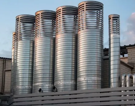
Mount the generator on a flat, vibration-free, level surface in a well-ventilated area, with clearance left around the body for filter changes, silencer replacement, and gauge access [S1]. Keep it away from dust, corrosive chemicals, and direct sunlight, and route the supply line away from heat sources that could push ambient air above the body's rated temperature range [S1][S2].
Follow ISO 4414 practice for the upstream air treatment: an FRL (filter-regulator-lubricator) train sized to the generator's peak Nl/min should sit within 5-10 hose diameters of the inlet, with the regulator set 0.2-0.5 bar below the maximum supply rating. The FRL unit installation walkthrough covers the upstream sequence in detail. Bolting pattern and torque values must come from the OEM bulletin; Parker CVM-201P, for example, is the document family to reference for its MCA-series generators [S2].
Plumbing the Inlet, Vacuum Port, and Exhaust
Use short, wide-bore vacuum-rated hose on the suction (vacuum) port to minimise conductance loss; sharp bends and kinks throttle the very flow the generator is trying to create [S1]. A foreline trap or inline filter on the suction line protects the nozzle from particulate, liquid carry-over, and dust that would otherwise erode the orifice within weeks [S1].
Exhaust must be vented through a silencer/muffler to atmosphere or, in cleanrooms, to an extraction manifold; never cap the exhaust, as back-pressure collapses the venturi's pressure-recovery stage and destroys suction capacity [S1][S2]. A comparison of the main options: short rigid pipework wins on conductance and cleanability, reinforced vacuum hose wins on vibration isolation and quick change-out, and quick-disconnect fittings win on tool changeover but introduce a leak point that must be checked each shift. For related plumbing-component decisions on the vacuum side, the ball valve types and body design fit reference helps with isolation-valve selection.
Electrical Setup and Solenoid Integration
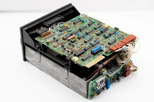
Match the solenoid coil voltage to the control supply (24 VDC is the packaging-line default; 110/230 VAC common on legacy panels), wire through a fuse or circuit breaker rated to the coil's inrush, and ground the generator body where the bulletin calls for it [S1][S2]. Parker's installation instructions require disconnecting electrical and pneumatic supplies before any service and re-testing for audible leakage and correct function before returning the unit to production [S2].
Integrate the solenoid with the PLC or relay control so the generator is only energised while suction is needed; leaving compressed air flowing to a venturi continuously is the single most common cause of high air consumption and downstream-actuator wear. Reference standard pneumatic safety guidance (disconnect supply, depressurise, operate within listed pressure/temperature limits, and have knowledgeable personnel perform the work) on every service event [S2].
Commissioning Checks: Leak Test, Vacuum Level, Cycle Response
Pressurise the supply with the vacuum port blanked off and confirm no audible leak at fittings, the silencer, or the body seam; any hiss at the generator's rated supply is a fail [S2]. Connect a calibrated vacuum gauge to the suction port and verify the unit reaches the OEM's published maximum vacuum within 2-3 seconds of solenoid energisation; sluggish pull-down points to undersized supply piping or a clogged silencer.
Cycle the solenoid at the application's planned duty rate (for example, 30 cycles/minute for a pick-and-place line) and watch vacuum recovery between strokes. If the gauge shows more than a 10-15% drop from peak between cycles, the air supply cannot keep up or the exhaust is restricted. A common culprit is an inline filter sized for a different flow regime than the generator, or a silencer that has wet oil mist loaded into it and needs replacement. Document the achieved peak vacuum and cycle time on the commissioning sheet so future drift is detectable.
Maintenance, Failure Modes, and When to Replace, Not Repair
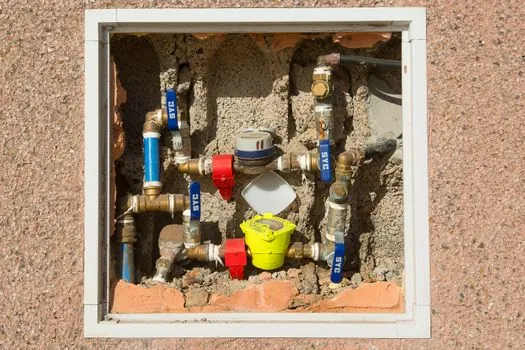
Three failure modes dominate: nozzle wear (vacuum level degrades over 6-12 months in dirty-air environments), silencer saturation (oil mist bleeds into the work area), and solenoid coil burn-out (typically from liquid carry-over or supply-voltage spikes) [S1][S2]. Replace nozzles when the achievable peak vacuum drops more than 15% from the commissioning baseline; cleaning them with wire probes only enlarges the orifice and accelerates the next failure.
Replace the silencer at every preventive-maintenance interval regardless of appearance; once the porous element is oil-loaded, vacuum performance drops and the mist becomes a contamination source. Do not repair solenoids in the field if the coil shows signs of thermal discoloration; coil failures cascade into rectifier and driver-board damage on the PLC side. For deeper plant-air quality issues feeding the generator, the linear guide reference covers the broader pneumatic-circuit discipline that keeps these components alive.
Trackable signals for the next planning cycle: (1) air-consumption trend on the upstream flowmeter, where a 10% rise at constant cycle rate usually means nozzle wear before the vacuum gauge has moved; (2) silencer differential pressure, which climbs as the element loads and is an early warning for both vacuum loss and oil-mist carry-over into downstream valves.