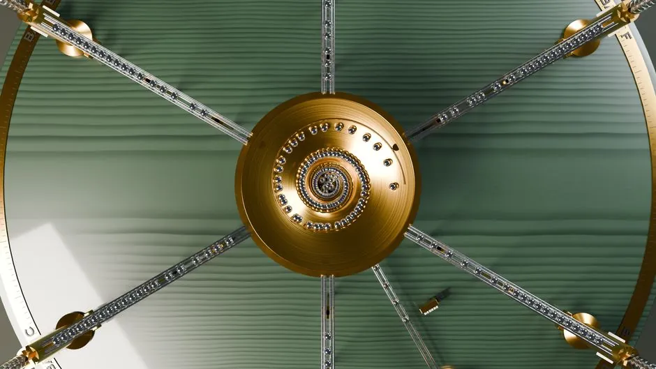
Choose a rack-and-pinion anti-creep cage when a crossed roller guide operates vertically, reverses repeatedly, or does not use its full stroke, because an unconstrained cage can drift, strike an end stop, and increase sliding friction [S1][S2].
The comparison covers cage positioning, load capacity, stroke use, mounting orientation, and integration effort for crossed roller guides using alternating rollers between V-shaped ways [S2][S3].
Cage creep mechanism and selection threshold
Cage creep is longitudinal movement of a non-recirculating roller cage away from its intended centered position, and gravity can cause this drift in vertical setups.
In vertical installations, gravity can cause the cage to drift, resulting in skidding, contact with end stops, cage wear, bending or cracking, and potential machine damage.
Specify an anti-creep cage when repeated short-stroke or reversing motion could cause the roller cage to walk out of position.
Rack-and-pinion versus standard cage
A rack-and-pinion anti-creep system uses gear engagement to resist relative longitudinal movement and maintain the cage's position.
The rack-and-pinion option is not a universal capacity upgrade. Its value is cage control, and the achievable load still depends on the selected size and roller population.
Applications where anti-creep is justified
The rack-and-pinion mechanism is used to hold the roller cage in position, while reduced roller pitch can fit more rollers.
Studs on a resin cage can roll into raceway depressions to prevent cage creep and allow rollers to be packed more closely. These are distinct mechanisms and should not be described as a rack-and-pinion system [S1].
Do not select anti-creep hardware merely because the application is labeled heavy duty. Use it where the operating mode creates a credible drift mechanism: gravity in a vertical axis, unused stroke at either end, reversing duty, or intermittent shock and vibration [S1][S6]. For general crossed roller selection principles, compare the cage architecture with the crossed roller guide range rather than treating anti-creep as a separate load class.
Limits, installation effects, and maintenance
Rack-and-pinion control introduces a second mechanical interface that must remain clean, correctly aligned, and free from binding. The source material establishes the functional arrangement, but it does not provide a universal allowable rack-and-pinion backlash value, lubricant requirement, service interval, or universal load derating, so those values must come from the selected manufacturer’s model data. [S1]
The anti-creep system does not eliminate the need to select the guide for the actual load and stroke. A guide can be excellent at cage control but unsuitable if its size, roller spacing, or mounting arrangement does not carry the applied load.
For standard cages, distinguish a resin retainer from a metal cage because rollers in a resin cage can sit closer together. The cage material and roller pitch must therefore be checked against load, accuracy, speed, and environment rather than treated as cosmetic options.
Procurement specification and acceptance checks
State the anti-creep mechanism by architecture, including whether a pinion integrated with the cage engages a rack integrated into one guide.
Include an end-stop strategy because a drifting cage can contact an end stop. Anti-creep control lowers that risk, but mechanical stops, travel limits, and the full-stroke envelope must remain part of the assembly drawing [S1][S2].
The next decision node is the supplier drawing: approve the anti-creep configuration only after the rack location, pinion integration, mounting orientation, load rating, and stroke limits are confirmed for the exact guide size and model.