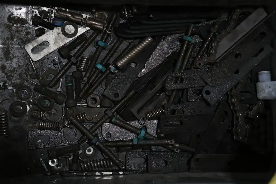
Rack sections can be joined for long travels, and rack-and-pinion drives avoid the screw-whip concerns associated with a long ball screw, but the appropriate choice depends on the axis.
The decision depends on travel, speed, load, accuracy, installation conditions and maintenance strategy, not drive type alone [S1][S2].
What Changes Beyond 3 m
A ball screw converts motor rotation into carriage motion through a threaded shaft, recirculating steel balls and a nut; its rolling contact supports fine feeding and reversal accuracy [S1]. As the screw length and unsupported span increase, dynamic stability becomes a design constraint. Laguna limits its ball-screw axes to under 4 ft and uses rack and pinion on X and Y axes measuring at least 4 ft [S3].
A rack-and-pinion system removes the full-length rotating-screw constraint. The pinion travels along a fixed rack, or a moving rack passes a fixed pinion, while joined rack sections extend the usable stroke [S1]. Rack and pinion is associated with large gantry machining centers, CNC routers, boring mills, laser cutters, and other long-stroke equipment.
That 3 m threshold is a practical screening boundary, not a universal rating. For systematic screw sizing, the ball-screw selection guidance for CNC feed axes provides a more appropriate basis than extrapolating from a short-axis catalogue.
Selection Criteria by Travel, Speed and Load
Travel is the first discriminator: rack sections can be joined end to end, whereas a ball-screw system requires a longer or specially engineered screw as travel increases [S1]. Speed is the second: rack and pinion avoids the full-length rotating shaft and remains better suited to long-stroke acceleration, while a long ball screw is constrained by critical speed and its diameter-to-speed relationship [S1].
Load requires separate treatment. A ball screw can develop high thrust when correctly sized, while rack capacity depends on module, material, heat treatment, pinion geometry and support arrangement [S1]. Rack sections also require a continuous rigid mounting surface. Laguna bolts guide rails every 4 in to its racks and uses a one-piece welded steel frame to limit wobble and vibration [S3].
Helical racks engage more teeth and provide smoother transmission than straight-tooth arrangements. These figures are vendor-specific and should not be transferred to another system without recalculation.
Ball Screw or Rack and Pinion

Ball screws are the better choice for short or moderate travel, compact integration, fine positioning, micro-feeding and machines requiring many reversals [S1][S6]. They also offer more mounting configurations and are generally easier to incorporate into an established manufacturing process than a rack-and-pinion installation [S2].
Rack and pinion is the better choice when stroke exceeds roughly 3 m, maximum speed is more important than micron-level positioning, or travel must scale through joined rack sections [S1]. Rack-and-pinion systems can produce for years with minimal wear and are favorable in stone and metals fabrication environments.
Over shorter distances, rack and pinion and ball screws compete, with ball screws able to offer higher precision and greater suitability for fine positioning.
Installation, Backlash and Maintenance
Rack and pinion transfers the alignment burden into the structure. Rack joints, rail spacing, frame stiffness, guide-rail support and pinion alignment must be controlled because side-to-side misalignment can cause binding [S1][S3][S4]. Laguna generally uses helical rack-and-pinion drives on the X and Y axes of its CNC routers and a ball screw on the Z axis.
Ball-screw installation still requires correct bearing support and alignment, but screw straightness, support span, end fixings and critical speed remain central to performance over the full stroke.
Maintenance expectations differ. Rack-and-pinion components can be replaced as bolt-on assemblies and the arrangement is comparatively tolerant of shop contamination [S2]. A ball screw requires nut preload, lubrication, return-system integrity and periodic inspection, while a long screw may need a larger diameter or more complex support than the rack alternative [S1][S2].
Best Fit by Machine Application
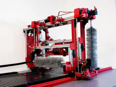
Specify a ball screw when travel is below about 3 m, the axis needs repeated fine positioning, the installation envelope is compact and the motion profile includes many low-load reversals [S1][S6]. Examples include precision positioning stages and compact machine-tool feed axes. The ball screw reference provides the relevant actuator terminology, while angular-contact bearings cover one possible support-bearing family.
Specify rack and pinion when travel is several metres, rapid traverse dominates the duty cycle, the machine is a large gantry or router, or contamination resistance matters [S1][S2]. A helical rack with a properly supported frame and a preloaded or dual-pinion arrangement is the preferred configuration for repeatability and backlash control [S2][S3].
Do not select a rack system solely for speed. If the specification requires micron-scale return accuracy across the full stroke, a long ball-screw arrangement with a larger supported screw may justify its greater installation effort. Conversely, a long ball screw selected only from catalogue diameter will not address whip, resonance, straightness or support stiffness [S3][S5].
Engineering Selection Checklist
Define usable stroke first, then calculate peak speed, acceleration, moving mass, axial load, duty cycle and required repeatability. For rack and pinion, verify rack and pinion module compatibility, tooth accuracy, joint layout, frame stiffness, guide-rail support, motor preload and contamination access [S1][S3].
For ball screw, verify the manufacturer’s critical-speed limit for the exact diameter, length, support arrangement and end-fixation configuration, not nominal speed alone [S1]. Also check nut preload, ball return arrangement, lubrication, screw straightness and support-bearing selection. Ball bearings are relevant where the screw support arrangement uses them, but the final selection must follow the screw supplier’s limits.
Use a functional prototype or motion simulation to compare completed-axis behaviour rather than component accuracy alone. For travel above 3 m, the default recommendation is rack and pinion when the required resolution permits it, and a carefully engineered ball-screw system when positioning precision is the governing requirement [S1][S4][S6].
Before releasing the design, record the confirmed stroke, rated and peak speed, positioning tolerance, repeatability, axial or transverse load, acceleration, lubrication method, support spacing and maintenance interval for both alternatives; these are the trackable values that determine whether the long-axis selection is defensible.