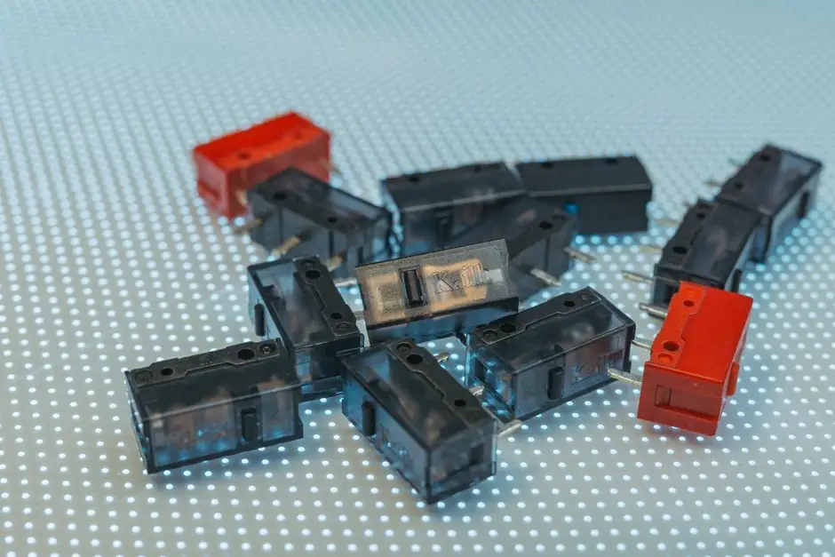
A mechanical pressure-switch microswitch can be replaced as a component when the replacement matches the original contact arrangement, actuator geometry, operating force, and electrical rating.
The repair covers HVAC, well-pump, furnace, pressure-washer, marine-pump, and industrial switch assemblies, but a generic microswitch is not automatically a drop-in replacement.
How the Microswitch Fits the Pressure-Switch Mechanism
A mechanical pressure switch converts fluid force into electrical switching through a piston or diaphragm, range spring, operating pin, insulated trip button, and microswitch. Fluid pressure moves the piston, overcomes the spring force, and pushes the operating pin into the trip button, which changes the microswitch contact state [S3].
The microswitch therefore performs the electrical function, while the spring and adjustment nut establish the mechanical operating range. Replacing only the microswitch preserves the original pressure-setting mechanism, but it does not correct an incorrectly adjusted spring, a seized piston, or a mechanical trip-point error [S3]. A pressure switch should be tested at both actuation and release points rather than judged only by whether the pump starts.
Common contact arrangements include normally open, normally closed, and changeover or SPDT. The replacement must reproduce the contact form used by the original wiring and control sequence [S3]. For a pressure switch controlling a motor, also record whether the contact is rated for the starting current of the controlled load, not only its steady-state current.
Select the Replacement by Four Independent Criteria
The second is actuation behavior, because the replacement must be pressed by the original operating pin and trip button at the intended pressure transition [S3].
The third criterion is mechanical fit. A practical microswitch installation sequence is to engage the rear of the replacement first, then rock the front downward until it snaps into the mounting position [S4]. The actuator must retain the original switch orientation, plunger travel, actuator position, mounting holes, and body clearance.
The fourth criterion is electrical and environmental capability. Check the voltage and current rating against the actual load, then verify the required contact protection and enclosure conditions. That example demonstrates why the internal component, complete assembly, and model number must be distinguished before ordering.
Remove and Install the Microswitch Safely
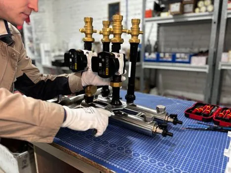
For a pressure-washer switch, isolate and unplug the machine before opening the electrical box. These mechanical disassembly steps create safe access to the switch enclosure, but they are model-specific rather than universal pressure-switch instructions.
Photograph the original wiring before cutting, remove the old switch leads and terminals, fit the replacement without changing actuator geometry, and reconnect the conductors to their recorded terminals [S2]. The broader microswitch method retains the rear engagement before rocking the front into place [S4].
Do not rely on wire color alone after a failed contact has heated or discolored the terminals. Inspect the conductor, crimp or solder joint, terminal, and actuator. Replace heat-damaged wiring rather than burying a loose connection inside the enclosure. For any switch near a combustible location, confirm the replacement's certified construction and installation suitability before energizing it.
Match the Load, Contact Type, and Failure Pattern
Contact selection starts with the load. A microswitch rated only for a control signal is not automatically suitable for directly switching a pump motor, compressor, heater, or solenoid. Contact arcing is a recognized wear mechanism in pump pressure controls, and rapid cycling accelerates contact erosion [S5].
The contact arrangement must also match the failure symptoms. An open circuit can prevent the pump from starting, while a contact that remains closed or leaks can allow the pump to run when it should stop. The microswitch opens and closes the electrical circuit when the sensed pressure reaches its preset level [S3].
For repairs involving a valve-position monitor, the same principles apply: diagnose the switch mechanically, remove it without disturbing the position-feedback mechanism, and preserve the actuator-to-target relationship during installation [S6]. This is different from replacing a pressure element or electronic pressure sensor, where signal output and calibration matter instead of a binary contact.
Test Actuation, Release, and Trip-Point Repeatability
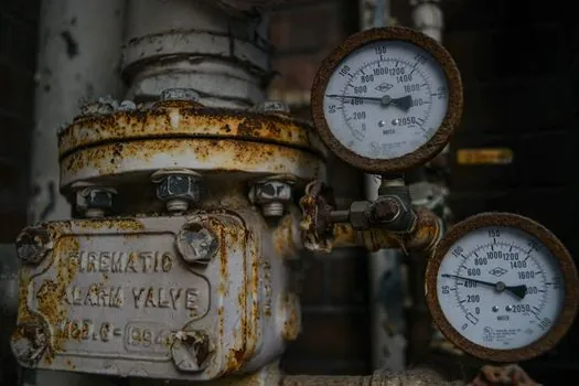
A successful replacement requires a functional test at both directions of pressure change. Apply pressure slowly and record the value at which the contact changes state, then reduce pressure and record the reset transition. For a manual-reset device, follow its documented reset conditions [S7]. The switching values should be compared with the pressure switch's adjustment range and the application's permitted operating limits.
Repeat the test at least three times and watch for contact chatter, an inconsistent trip point, or a contact that fails to return cleanly. Reconnect and test the controlled load under its normal operating condition, including motor starting current where applicable. A microswitch can pass a bench continuity check and still fail when carrying the inrush current of a pump [S5].
Do not adjust the range spring to conceal a poor microswitch. The spring, operating piston, operating pin, and trip button define the mechanical action, while the microswitch only opens or closes the circuit [S3]. If pressure does not change exactly when the operating pin reaches the replacement switch, inspect travel, alignment, mounting position, and adjustment rather than increasing electrical load on the contacts.
Identify Limits Before Ordering a Part
A microswitch with the correct number of terminals is not necessarily electrically or mechanically equivalent. A 125PC05D1 sensor example had four terminals and six resistance measurements ranging from 3.29 kΩ to 5.20 kΩ, demonstrating why terminal count and resistance readings alone do not establish compatibility [S1]. That unit was produced in 1989 and had no located replacement, so its serviceability depended on an unverified substitute rather than a confirmed catalog match [S1].
That case also demonstrates a distinction often lost in repair work. The MICRO SWITCH-marked 125PC05D1 was a four-terminal differential-pressure sensor on an RT-200 flow-module board, supplied by ±14.5 V and associated with amplifier circuitry, not a conventional three-terminal snap-action pressure-switch microswitch [S1]. Its measured output shift from 0.15 mV to 0.33 mV was diagnosed as thermal-stability failure [S1].
For a conventional mechanical pressure switch, require a legible part number or manufacturer datasheet, verified contact form, actuator type, terminal layout, switch dimensions, operating force, travel, electrical rating, and environmental rating. Where the original documentation is unavailable, preserve a failed switch for measurement and bench comparison. A pressure calibrator can verify applied pressure, while a pressure gauge provides an independent indication for trip-point comparison.
Repair Is Justified When Fit and Testing Are Conclusive
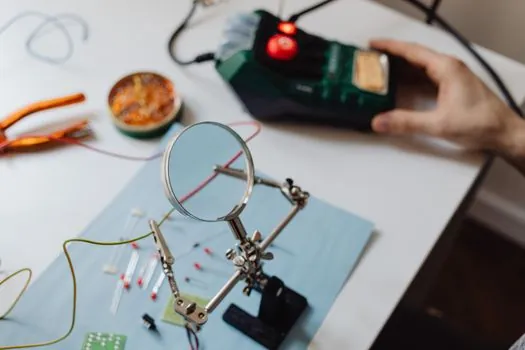
Replacing the internal microswitch is economical when the pressure element, spring, piston, pin, trip button, wiring, and enclosure remain serviceable and the replacement matches all four functional criteria. It is unsuitable when the device uses a nonstandard pressure sensor, when the original actuator cannot be reproduced, or when the application requires a contact arrangement or interrupting rating outside the replacement's specification [S1][S3].
The acceptance record should include the switch model, contact arrangement, actuator orientation, measured actuation pressure, measured release pressure, number of successful cycles, and connected load. The 13-minute Shurflo repair example places its initial switch test at approximately 1 minute 20 seconds, while the documented pump-switch replacement separates the internal microswitch from complete assemblies 94-800-05 and 94-801-05 [S5].
Track two signals after repair: whether the contact changes at repeatable pressure values, and whether the controlled load stops cleanly without rapid cycling or contact damage. Those results determine whether the replacement restored the switch or merely moved the failure to another component.