
A raw bridge sensor typically provides a low-level millivolt signal, while a conditioned transmitter converts that output into a standardized 4–20 mA, 0–10 V, or digital industrial signal [S2][S6].
The practical selection boundary is integration distance, noise immunity, calibration responsibility, and whether the pressure measurement must feed a PLC, controller, or remote monitoring system [S4][S5].
Raw Sensor Output vs Transmitter Output
The defining difference is signal processing: a pressure sensor converts pressure into an electrical response, whereas a pressure transmitter adds amplification, linearization, compensation, and standardized output for control-system integration [S3][S7].
A typical raw bridge output is expressed in millivolts, often as mV/V, and requires external amplification, excitation, and calibration. A transmitter can produce 4–20 mA, 0–5 V, or 0–10 V, with 4–20 mA being the most common industrial current-loop output [S2][S3][S6].
For remote or noisy installations, a conditioned transmitter is normally the better engineering choice because the output is stronger, standardized, and less vulnerable to degradation over long cable runs [S4]. The related pressure sensor output selection guide covers the signal and protocol decisions in more detail.
Selection Criteria That Decide the Architecture
Choose a raw sensor when the electronics are part of the equipment design, the wiring is short, and the OEM controls excitation, analog input modules, compensation, and calibration [S4][S5]. This can reduce component count, but it transfers engineering responsibility to the integrator.
Choose a conditioned transmitter when the sensor must connect directly to a PLC input, remote indicator, control loop, or plant network. The transmitter handles the raw signal and produces a usable industrial output, reducing field integration effort [S2][S5].
Evaluate at least four criteria: output format, cable distance, environmental noise, and maintenance responsibility. A 0–10 V output is convenient for short links, while 4–20 mA is generally better suited to remote transmission and electrical-noise rejection [S3][S6].
Do not confuse output type with measurement function. Gauge, absolute, differential, and sealed-gauge references determine what pressure is being measured, while the output determines how the value reaches downstream equipment. A transmitter does not automatically make a gauge sensor a differential device.
Comparison of the Main Options
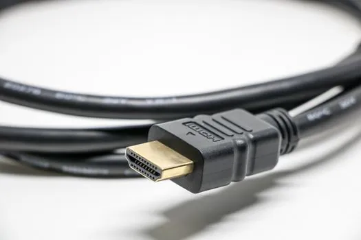
Raw pressure sensors offer the lowest integration cost when the OEM already owns the signal chain, but they require short wiring, low-noise routing, and careful calibration [S4][S5]. Their millivolt output can be useful inside laboratory, test, or machine-mounted systems.
Packaged transducers occupy the middle ground. They generally provide a more usable voltage output than a raw bridge, such as 0–5 V, while retaining a smaller integration burden than a full process transmitter [S3][S5]. They suit OEM machinery and local control assemblies where standard voltage signaling is sufficient.
Conditioned transmitters provide the strongest industrial fit for long-distance transmission and remote monitoring. Typical outputs include 4–20 mA, 0–5 V, and 0–10 V, with the transmitter performing amplification and signal conditioning before the signal reaches the controller [S3][S6].
Where Raw Sensors Work Best
Raw pressure sensors are appropriate when pressure is measured close to the acquisition electronics, the enclosure is controlled, and the design team can provide stable bridge excitation and input protection [S4][S5]. They are especially useful when product size, component cost, or custom packaging takes priority over field-ready instrumentation.
Example core devices include pressure sensors that measure pressure and convert it into an electrical signal, while transmitters add signal conditioning, amplification, and calibration for reliable transmission [S2].
For OEM pressure measurement, the raw device is not a complete measurement system. The integrator must define excitation, input-common-mode limits, zero and span trim, temperature compensation, calibration records, EMC behavior, and the final output range [S5]. A bench-calibrated element can still fail in service if those details are left unspecified.
Where Conditioned Transmitters Work Best
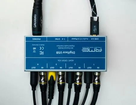
Conditioned transmitters are the practical choice for pipelines, power plants, water treatment, chemical production, food and beverage processing, and other remote process installations [S2][S3]. They provide a standardized signal that can travel to controllers and monitoring systems with less field intervention.
For 4–20 mA loops, the useful diagnostic property is that 4 mA represents the lower output state and 20 mA represents the upper output state, while a value between them carries the measurement. The two-wire loop-power relationship should be checked at design stage; two-wire loop power in a 4–20 mA pressure transmitter addresses that constraint directly.
Conditioning does not eliminate mechanical or media-related failure modes. Corrosive fluids, particles, moisture, and temperature cycling can still damage the wetted assembly or cause drift [S5]. For exposed process taps, specify compatible wetted materials, an appropriate isolation structure, and suitable enclosure protection before choosing the output architecture.
Limits, Failure Modes, and Calibration Scope
The principal limitation of a raw sensor is not pressure detection itself; it is the burden placed on the receiving electronics. Long cables, EMI, grounding errors, moisture ingress, and temperature cycling can turn a workable bench signal into an unreliable field measurement [S5].
The principal limitation of a transmitter is less signal-chain work, but more device configuration and specification work. The integrator must still verify range, overpressure capability, accuracy, environmental rating, electrical isolation where required, output direction, and compatibility with the receiving controller [S3][S4].
Static calibration may be adequate for many continuous processes, while dynamic calibration becomes necessary when pressure changes rapidly enough to affect the measurement chain. Industrial applications can require dynamic characterization even for variations in the tens-of-hertz range or below, including pump pulsation and deaerator measurements [S1].
Calibration terminology also needs care. A stated accuracy figure does not by itself define the complete error band, and a transmitter datasheet should distinguish accuracy, repeatability, hysteresis, temperature effect, and long-term stability. The related pressure transmitter calibration interval parameters are useful when setting inspection intervals.
Engineering Recommendation by Application
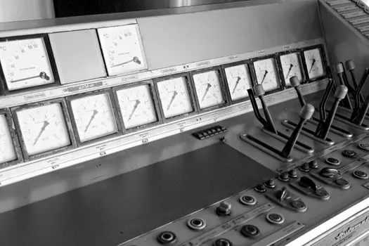
For a short cable run inside an OEM machine, use a raw sensor only when the product team has established the complete analog measurement chain. If the team wants a ready-to-connect voltage output, use a packaged transducer. If the pressure point is remote, noisy, or must feed a PLC loop, use a conditioned transmitter with 4–20 mA output [S3][S4][S5].
For differential applications, the decision remains the same but the sensing element must also support differential pressure. A differential pressure transmitter adds the measurement reference and industrial signal package that a single-ended raw sensor does not provide.
Record the selected output, excitation requirements, calibrated range, accuracy definition, temperature range, cable type, grounding arrangement, and loop-power budget before releasing the instrument specification. These are the traceable items that determine whether the installed measurement matches the bench component.