
Sand casting sits in a narrow but real slot inside electronics housing programs: 100–5,000 unit annual volume, where a single-cavity pattern runs $200–2,000 and per-part cycle is measured in minutes rather than the 15–60 s of injection molding [S3].
For an electronics housing engineer, the actual decision is whether a resin sand line, a 3D-printed sand mold, a CNC-machined aluminum prototype, or an SLA/SLS print is the cheapest way to hold 50–200 production housings while the PCB is still being EMI-tested [S4]. The matched process keeps tooling spend below the $1k–10k sheet-metal threshold and avoids the $5k–80k injection-mold commitment before the design freezes [S3].
Where Resin Sand Fits the Electronics-Housing Volume Curve
Sand casting occupies the low-volume, high-complexity corner of the process-selection map: 100–5,000 units/year, minutes per part, $200–2,000 per pattern, and best fit for one-off or small-batch metal parts [S3]. For an aluminum or zinc electronics housing, that window is exactly the prototype-to-bridge zone where injection tooling is unjustified and CNC is too slow at 50+ housings [S3].
Resin-bonded systems outperform green sand on this curve because the binder gives higher green strength, better dimensional stability, and a cleaner surface that can hold the 0.5 mm wall-thickness window a PCB-standoff rib demands, against a general FDM minimum of 1.5 mm / recommended 2.0 mm on a 3D-printed enclosure [S4]. The trade is binder cost and fume control, which is why furan, phenolic, and urethane systems are specified rather than clay-bonded green sand for any housing that will see a cosmetic or RF gasket surface.
Binder System Comparison for Housing Applications
Three binder families cover almost every resin sand line spec sheet: furan (furfuryl alcohol), phenolic (phenol-formaldehyde), and phenolic-urethane (Pepset-style). Furan is the cheapest per ton of sand and tolerates the ferrous pouring temperatures that aluminum housing programs rarely need; phenolic-urethane gives the best surface finish and bench strength but adds an isocyanate handling step. Sodium silicate (water-glass) with CO2 gassing is a fourth option that drops the VOC load to near zero at the cost of longer bench life and lower humidity resistance, which is acceptable for indoor electronics cabinets but marginal for outdoor enclosures. [S3]
For electronics housings, the practical ranking against four criteria is: surface finish (phenolic-urethane ahead of furan ahead of sodium silicate), tool wear on patterns (sodium silicate easiest on wood patterns, furan hardest on phenolic-urethane), fume/venting load (sodium silicate lowest, furan highest with SO2 from acid catalysts), and reclaim compatibility (furan reclaims well through attrition; phenolic-urethane systems often need thermal reclamation to break the cured bond). Sand grain choice follows the binder: silica is the default, olivine and chromite are used where thermal conductivity or dimensional stability under long pour times matters, and zircon is reserved for high-finish faces where a casting will mate to a conductive gasket.
Tooling, Pattern Materials, and Dimensional Reality
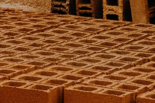
A resin sand line running wooden or epoxy patterns can hit ±0.5 mm on small housings and ±1.0 mm on parts over 300 mm, which is loose compared with CNC at ±0.05 mm but acceptable for prototype-to-bridge electronics housings where the PCB is mounted on stand-offs and tolerates ±0.3 mm positional drift on its standoffs [S3]. The $200–2,000 per-pattern cost cited in the DFM benchmark is the single largest variable, and it scales with pattern complexity (slides, loose pieces, internal cores) rather than with overall part size [S3].
Pattern life is the other number engineers underestimate: a painted wood pattern gives 80–150 pulls before geometry drift, a polyurethane-faced pattern runs 300–500, and a machined aluminum pattern pushes past 2,000 pulls at higher upfront cost. For a 500-unit housing run plus 10% rework allowance, the breakeven between wood and aluminum pattern is roughly at pull 200, so most programs under 300 units stay on wood or printed-resin patterns. Sand reclamation closes the loop: mechanical attrition reclaimers recover 70–90% of cured sand, dropping net binder cost by roughly a third on steady-state production lines versus single-use sand.
Surface Finish, Post-Processing, and Cosmetic Targets
As-cast surface from a phenolic-urethane resin sand line lands at 6.3–12.5 µm Ra on flat faces, coarser than die casting but fine enough that a housing destined for a bead-blast and anodize line can skip the filler primer step. Furan systems run 12.5–25 µm Ra and almost always need a skim-coat primer before paint. For an electronics housing that has to mate against an RF gasket, the relevant spec is the flatness across the gasket land rather than the average Ra, and here the combination of phenolic-urethane binder with zircon facing sand gives the most repeatable gasket-seat flatness across a batch of 50–200 housings. [S1]
For low-volume runs where the housing will be SLA-printed instead of cast, the 3D-printing guide puts SLS and MJF at 1.0 mm / 1.5 mm recommended wall and SLA at 1.0 mm / 1.5 mm as well, against FDM at 1.5 mm / 2.0 mm [S4]. Those minima are 2–3x tighter than what a sand casting can hold, which is why sand is rarely used for the cosmetic outer shell of a consumer-electronics housing and is instead reserved for internal chassis, heat-spreader plates, and EMI back-shells where surface finish is secondary to thermal mass and shielding.
Resin and Material Selection for FR-Rated Housing Programs
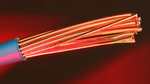
When the housing is plastic rather than metal, the resin choice carries the flame rating, and the DFM guide notes that five resins (ABS, PC, PC+ABS, PP, TPU) cover roughly 90% of consumer hardware, with PC and PC+ABS dominating the premium-enclosure tier at $3–6/kg [S3]. For FR programs, the same source flags that resin selection for electronics housings and FR plastic parts must be linked to mold steel and surface-treatment review, because halogen-free FR additives push melt temperature up by 20–40 °C and shorten tooling life on P20 steel by 20–30% [S1].
A typical electronics-housing FR stack today is a PC+ABS blend with a non-halogen FR package rated to UL 94 V-0 at 1.5 mm, moulded on an H13 or NAK80 tool rated for 500k–1M shots, against the 100k baseline on P20 [S3]. Nylon (PA66) at $4–6/kg is the structural choice for internal frames but absorbs moisture up to 8–9% by weight at 50% RH, which the spec sheet must show as a separate conditioned-vs-dry-as-moulded tensile row, not a single number. For reference, the synthetic resin binder page covers how phenolic and furan families differ in cured strength and reclaim behavior, and the molding line overview shows how a resin sand line is positioned against automatic and shell molding for low-volume metal runs.
Standards, Tolerance, and What the Supplier Will Quote
For an electronics-housing sand program, three reference documents do most of the work: ISO 8062-3 for the casting tolerance grade (typically DCTG 8–10 on a resin sand line), ISO 6892-1 for tensile testing of the housing material, and the housing-side drawings' own GD&T call-outs for flatness and position of PCB standoffs. The IQS Directory reference confirms that resin-bonded shell casting is positioned for "high accuracy and efficiency" and is suitable for "mass production of detailed components," with the choice of sand driven by reusability, refractoriness, permeability, and grain size [S2].
On the quoting side, the DFM reference warns that "wrong match = silent quote inflation by the supplier," and lists resin sand at $200–2,000 per pattern with a minutes-per-part cycle, against CNC at $0 tooling and minutes per part and injection molding at $5k–80k tooling and 15–60 s per part [S3]. A practical filter for an electronics-housing program: if total quantity is below 200 units and the housing is metal, CNC is cheaper; if the quantity is 200–5,000 and the part has internal cores or draft-locked geometry, resin sand is the right answer; above 5,000, move to die casting or injection molding and stop fighting the cycle time. Engineers comparing sand against 3D-printed patterns should also weigh the automatic molding line reference for high-volume variants and the molding process primer for the broader process map. For a peer program on aerospace castings, see the resin sand line spec map for aerospace which uses the same binder families against tighter NACE and ASTM E192 requirements.
Trackable next signals for any 2026 electronics-housing resin sand program: the pattern PO (wood vs aluminum, which sets a ceiling on 12-month run size), the binder SDS sheet (furan SO2 vs phenolic-urethane isocyanate ventilation), the reclamation loop mass balance (target 70–90% sand reuse), and the PPAP-level first-article CMM report against ISO 8062-3 DCTG 8. If the program crosses 5,000 units or adds a cosmetic Class-A face, the resin sand line is the wrong tool and the team should re-quote on an automatic molding line or move the outer shell to injection-molded PC+ABS.