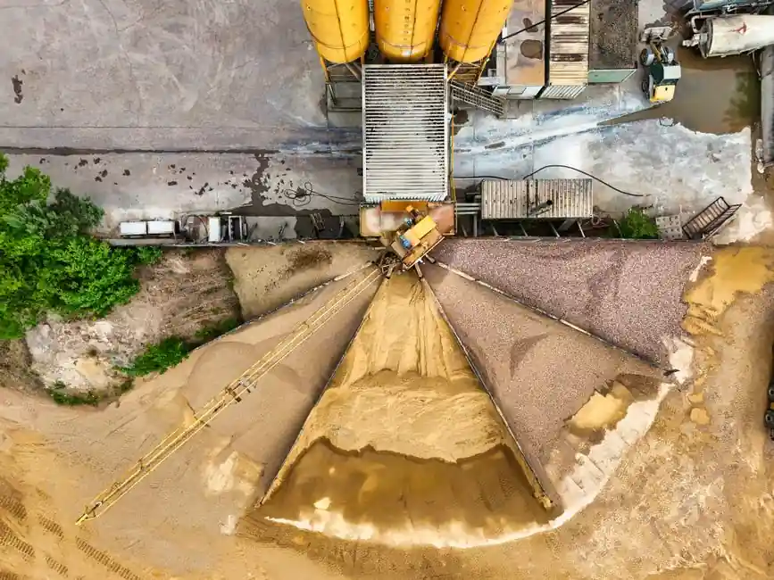
Cement plants punish retaining rings with three concurrent stressors: airborne cement dust that infiltrates every clearance, sustained ambient temperatures of 80 to 200°C around preheater and cooler service, and vibration amplitudes of 5 to 15 g on crusher and screen shafts. Selection logic that works for packaging machinery or HVAC fans fails inside a raw mill or kiln drive, where radial groove load, thermal expansion, and contamination converge.
Engineers working in cement, lime, and aggregate operations should treat retaining ring choice as a function of four variables: assembly type (shaft vs housing), thrust capacity, installation method, and the exposure profile of the specific station. Each of these maps differently to the dust-heavy, high-temperature zones of a cement line.
Defining the Service Environment for Retaining Rings in Cement
Retaining rings create an internal or external shoulder to retain bearings, seals, couplings, and sprockets on shafts and in bores, and they reduce manufacturing complexity versus a machined shoulder [S3]. The component is small but its failure mode is not: a deflected or fractured ring inside a gearbox or crusher takes the surrounding assembly with it, and mean time to repair in a kiln or cement mill routinely runs 24 to 72 hours once a bearing housing is breached.
Cement plant exposure is more aggressive than general industrial use. Raw mill separator bearings sit in dust-laden air, kiln idler stations see continuous thermal cycling, and crusher shafts transmit shock loads every time a clinker fragment breaks. Each of these stations drives different specification choices for the retaining ring, and the dominant failure mode is deflection of the ring under thrust, not the fastener itself unwinding as on a threaded part [S5].
Selection Criteria: Internal vs External, Thrust Capacity, and Material
Step one in any retaining ring specification is internal vs external: internal rings sit in a housing groove to retain a part inside a bore, while external rings sit in a shaft groove to retain components on a shaft, and all standard rings are designated as one or the other with the exception of an OD/ID lock ring that functions in both roles [S4]. In a cement plant, internal rings show up in gearbox housings, trunnion bearing caps, and cooler fan casings; external rings are more common on crusher shafts, conveyor idlers, and kiln drive couplings.
Step two is thrust capacity. Tapered-section rings (snap rings, circlips) typically support the highest thrust loads, radially installed rings accommodate less force than axial rings when thrust loading is secondary, and self-locking push-on rings provide the lowest thrust capacity but require no groove at all [S1][S3]. For crusher and mill applications, where shock loads routinely exceed 50% of static thrust, engineers should move to reinforced or heavy-duty designs: the reinforced E-ring grips the groove bottom with 3 to 5 times the radial force of a standard E-ring and offers greater resistance to fatigue failure under cyclic loading [S5].
Step three is material. Standard carbon steel works in clean, moderate-temperature zones, but cement plant housings near the kiln or preheater tower commonly see 150 to 200°C ambient with chloride-bearing dust. Stainless steel (typically 302 or 17-7PH) and zinc- or phosphate-coated carbon steel are the practical options; Spiral Retaining Rings from Smalley, for example, are offered in a variety of alloys to suit specific environmental demands [S1][S2].
Ring Type Comparison: Tapered, Constant Section, Spiral, and Self-Locking

Four ring families dominate cement plant service, and the decision between them is rarely a wash. The comparison below uses the four criteria that matter most in abrasive, high-vibration service. [S2]
Tapered-section rings (external/internal circlips, snap rings) carry the highest thrust per cross-section, use lug holes for installation, and come in sizes from 1 mm to 1200 mm per Rotor Clip, but the radial projection of the lug creates interference with adjacent components and the stamped cross-section has less fatigue margin than wound wire [S1].
Constant section (snap) rings provide uniform width and three-point contact with the groove, are economical, and work well in tight clearances, but they are harder to install because they have no lug holes, and they offer no special advantage under vibration [S1][S3].
Spiral retaining rings, whether single-turn or multi-turn Spirolox, deliver 360° contact with no gap, no lugs, and uniform cross-section for even load distribution; multi-turn versions are groove-interchangeable with most stamped snap rings and require no special tooling for installation or removal [S1][S4]. For crusher shafts and conveyor idlers in cement plants, spiral designs are often the best fit because the absence of a lug gap eliminates a high-stress initiation point under reversing loads.
Self-locking and push-on rings need no groove, install nearly anywhere along a shaft, and tolerate moderate vibration, but their thrust capacity is the lowest of any family and they are best reserved for covers, guards, and low-load idler retainer applications [S1][S3].
Groove Geometry and the DIN 471/472 Question
Most retaining ring failures in cement service are groove-related, not ring-related. Both groove walls must be parallel and perpendicular to the axis of the shaft or housing, and groove depth directly controls the support the load-bearing groove wall provides; the edge margin (the distance from groove to shaft end) has been calculated to provide sufficient material to resist shearing under maximum loads [S5]. Sharp corners on the retained part provide ideal contact with the ring's protruding section, while a radius or chamfer on the retained part compromises thrust capacity and can lead to ring deflection under extreme loads [S5].
For a 1 in. housing, a typical Smalley WH-100 two-turn housing ring sits in a 1.043 in. groove diameter and 0.042 in. groove width, and standard sizes are stocked from 1/4 in. to 16 in. (6 mm to 400 mm) in both carbon and stainless steel [S4]. Metric cement plant designs built to European OEM prints normally reference DIN 471 (external) and DIN 472 (internal) groove dimensions, while ANSI B27.7 covers the inch-series groove geometry. Engineers should always confirm which standard governs the drawing before ordering, because DIN and ANSI groove depths and widths are not interchangeable across the same nominal shaft diameter.
Cement Plant Use Cases: Where Each Ring Type Earns Its Place
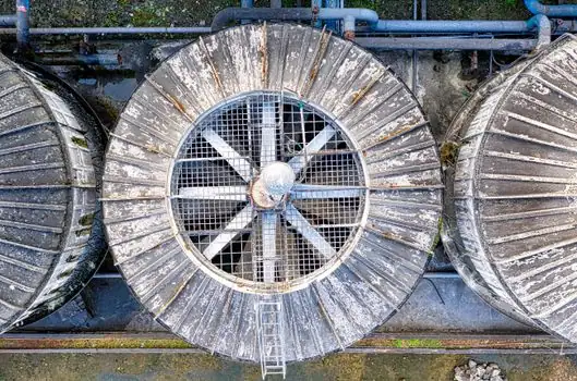
Crusher shafts (jaw, impact, hammer) carry shock loads every cycle and are exposed to cement and limestone dust. Reinforced E-rings or multi-turn spiral rings in 302 stainless are the workhorse choice; the 3 to 5 times higher radial grip of a reinforced E-ring is decisive where vibration and RPM are high [S5].
Rotary kiln trunnion bearings run slowly but at temperatures of 150 to 200°C with continuous thermal cycling. Here the priority is stable groove contact under thermal expansion; spiral or heavy-duty tapered rings in stainless steel, sized with extra edge margin to allow for shaft growth, are standard practice.
Conveyor idlers and pulley shafts see moderate thrust but heavy dust exposure. Self-locking push-on rings work for the lighter end (idler covers, end caps), while external tapered or spiral rings retain the bearing inside the idler housing. For heavy-duty conveyors carrying clinker, the increased fatigue margin of a spiral ring is worth the modest cost premium over a standard stamped circlip.
Cooler and preheater fan shafts combine high RPM (1500 to 3000) with dust-laden air at 100 to 200°C. Multi-turn spiral retaining rings in stainless steel are the common specification because they offer 360° contact, balanced load distribution, and no gap to initiate a fatigue crack under dynamic loading [S1][S4].
The mining and heavy-industry case study base provides useful cross-reference: a related retaining ring selection for mining guide covers similar shock-load and abrasion trade-offs applicable to raw material handling upstream of the kiln.
Who Retaining Rings Are For, and Where They Should Be Replaced
Retaining rings are the right answer when a shoulder is needed on a shaft or in a bore and machining a shoulder is impractical or uneconomical [S3]. They are the wrong answer when thrust loads exceed what a stamped cross-section can carry without deflecting, when temperatures push past the coating or material limit, or when the application needs a true bearing surface rather than a single-point retainer.
For very heavy loads, the reinforced ring outperforms the basic ring because of greater section height, lug shape, and thickness, and reinforced versions may also remedy instances of fatigue failure [S5]. Where load is not critical but the lug protrusion of a basic ring creates interference with a mating component, an inverted ring is the cleaner choice; inverted and basic rings share the same groove dimensions, so they are interchangeable as far as machining is concerned [S5].
Sourcing, Standards, and Procurement Notes for Cement Operators
Standard inch-series retaining rings from Smalley are stocked from 1/4 in. to 16 in. (6 mm to 400 mm) in carbon and stainless steel, with 6,000 standard parts and 30 configurations available off the shelf [S4]. Multi-turn Spirolox rings, depending on configuration, cover medium-duty (1/2 in. to 11 in.), medium-heavy (1/2 in. to 10.5 in.), and heavy-duty (1/4 in. to 15 in.) envelopes [S4]. Rotor Clip manufactures every style of retaining ring, including tapered-section, radially installed, self-locking, constant section, spiral, and custom configurations, in standard sizes from 0.040 in. to 47 in. (1 mm to 1200 mm) [S1].
For cement plant procurement, three checks reduce unplanned outages: confirm the standard governing the groove (DIN 471/472 vs ANSI B27.7 vs JIS B 2804), verify that the material certification matches the temperature and contamination profile, and stock reinforced or heavy-duty variants for any crusher or mill shaft with a documented shock-load history. A retaining ring costs cents; the bearing it retains costs thousands, and the kiln day lost to a deflected ring costs more than both.
Track these signals going forward: cement plant rebuilds shifting toward spiral rings for kiln and cooler service, expanded stainless offerings from major ring manufacturers, and any new edition of DIN 471/472 or ANSI B27.7 modifying groove tolerances for high-temperature service. Each of these is a leading indicator of where the next specification revision will land.