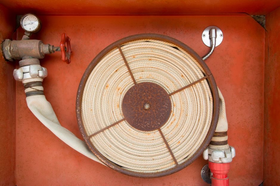
Every safety relief valve (SRV) is sized by the equation mandated in ASME BPVC Section VIII, UG-127 through UG-131, where the required discharge area A is set by the largest single contingency (external fire, blocked outlet, control-valve failure, or tube rupture) on the protected vessel [S2].
The selection chain runs in this order: identify the code case (air, steam, water, or vapour/gas with known Kd), compute W or W in kg/h, pick a standard orifice letter (D through T, with corresponding area in mm²), then match body, bonnet, spring, and seat material to the fluid and the ASHRAE 15 / IIAR / PED requirements that apply to the installation [S1]. For a 1/2" FPT inlet refrigerant valve, for example, the Parker SR series publishes a standard pressure-relief band of 150, 250, 300, and 400 psi with stainless internals and a PTFE seat disk, certified to ASME BPVC and stamped UV/NB by the National Board [S1].
Sizing Inputs: Code Case, Set Pressure, and Overpressure
The first numeric decision on any SRV job is the set pressure (PSV set) versus the vessel MAWP, which ASME BPVC Section VIII restricts so that set pressure ≤ MAWP and accumulation (typically 10% for fire case, 16% for non-fire on unfired vessels) defines the required relieving capacity [S2].
For non-fire single-contingency cases on fired or unfired vessels, the 16% accumulation limit is the usual design ceiling; the 10% fire-case limit kicks in only when an external fire is the controlling scenario and the vessel is unprotected by insulation or firefighting [S2]. Required capacity is read off the heat-input tables in API 521 (wetted surface formula) or, for refrigerant pressure vessels, off ASHRAE 15 ambient-shading tables; the two paths routinely diverge by a factor of 3-4 on the same vessel, which is why the controlling case must be declared before the orifice is picked [S1].
Relieving temperature, backpressure (built-up vs superimposed), and fluid phase at the inlet are the next three numeric inputs; they decide between a conventional (limited backpressure ≤ 10% of set) spring valve, a balanced-bellows design, or a pilot-operated valve where built-up backpressure exceeds roughly 30% of set [S2].
Valve Types by Orifice and Service
Orifice letters run D, E, F, G, H, J, K, L, M, N, P, Q, R, and T in API 526, with effective areas from about 71 mm² (D) to roughly 1845 mm² (T), so a single size jump can multiply required capacity by 1.6× and skipping a letter either under-sizes the valve or wastes bonnet envelope space [S2].
Service-band mapping that a senior engineer applies first: (1) Refrigerants R22, R134a, R404A, R717 and HFCs — conventional spring valve, stainless internals, PTFE or soft seat, MAWP classes 150-400 psi, 1/2"-1" FPT inlet per ASHRAE 15 [S1]. (2) Steam — full-lift conventional or balanced-bellows depending on superheat, set pressure typically 15-300 psig, body in cast steel or WCB [S2]. (3) Compressed air and inert gas — full-lift conventional, maximum allowable pressure drop across the inlet ≤ 3% of set to avoid chatter [S2]. (4) Cryogenic LNG/LOX/CO2 — extended-bonnet with a cold box ≥ 300 mm, austenitic stainless trim, and a PCTFE seat rather than PTFE, since PTFE loses integrity below roughly -50 °C. A buyer who skips the service-band check and orders a generic brass-bodied air valve onto a -160 °C LNG line gets a brittle-fracture incident, not a specification discussion.
Selection Criteria: Body, Trim, Seat, and Bonnet
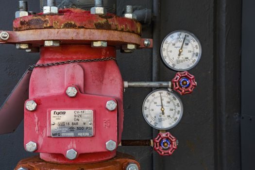
Body material is driven by corrosion allowance, not just pressure class: carbon steel (WCB) covers most hydrocarbon service up to 425 °C, low-temperature carbon steel (LCC) is required below -29 °C per ASME B31.3, and austenitic stainless (CF8M / 316SS) is the default for chlorides, wet CO2, and ammonia where stress-corrosion cracking is a documented risk [S2].
Seat and disk materials are where 80% of field failures actually start, so they belong on the datasheet, not as an afterthought: PTFE seats handle most refrigerants and chemicals to roughly 200 °C; metal-to-metal Stellite #6 or Inconel 600 trim is the call for steam and high-temperature hydrocarbon; PCTFE or PEEK replaces PTFE on cryogenic and low-temperature chemical duties where PTFE hardens and cracks [S1]. Spring material must be matched to the set pressure × temperature combination, with Inconel X-750 springs required above 230 °C where carbon-steel springs suffer creep and set-pressure drift. A PTFE seat on a refrigerant valve is the supplier's mark that the fluid chemistry is benign; the absence of a PTFE or soft-seat reference on a quoted valve is a flag to re-check service compatibility before accepting the bid.
Inlet/Outlet Sizing, Manifolds, and Rupture-Disc Stacks
ASME BPVC Section VIII UG-127 requires the valve inlet to be no smaller than the vessel or line nozzle it protects, and the outlet to be sized so that reaction forces during discharge do not exceed the manufacturer's published limit for the bolted joint; ignoring the inlet rule is the single most common reason a passed factory-set valve still fails to relieve at the required capacity [S2].
Manifolded (dual or triple) valves are used on continuous service where the SRV cannot be taken offline for testing: Parker publishes an M1 manifold in 1/2", 3/4", 1" and 1-1/4" sizes, designed to meet ASME VIII, ASHRAE 15, and IIAR simultaneously [S1]. Rupture-disc assemblies stacked upstream of an SRV are a separate selection problem: the disc bursts at roughly 90% of the SRV set, the disc-holder adds a net flow-resistance (Kr) that the user must include in the effective orifice area, and a vacuum-side disc is mandatory on any vessel where inward collapse pressure is below 0.5 bar absolute, which covers most atmospheric low-pressure storage tanks.
Compared to the alternatives, a spring-loaded SRV scores highest on simplicity and lowest unit cost; a rupture disc plus SRV (RD-SRV) stack scores highest on fugitive-emission sealing and corrosive or polymerising service; and a pilot-operated SRV scores highest on close-tolerance set pressure and high-capacity / small-orifice envelope. The trade-off is operational: a pilot-operated valve requires a sense line, has more field-adjustable parts, and costs 2-4× the equivalent direct-spring valve at the same orifice size [S2].
Standards Stack, Certification, and Field Inspection
The regulatory stack on a typical US or EU installation runs ASME BPVC Section VIII for the vessel and valve, ASME B31.3 for the piping, ASME PTC 25 for flow-rating verification, API 520/521 for sizing methodology, API 526 for flange dimensions and orifice letters, and on the EU side PED 2014/68/EU with CE marking, plus ATEX 2014/34/EU if the relieving fluid is flammable and the discharge point sits in a classified zone [S2].
Each valve must carry the UV stamp (American Society of Mechanical Engineers) and NB stamp (National Board of Boiler and Pressure Vessel Inspectors) before it can be installed on a Section VIII vessel in the US; the equivalent for the EU is the PED conformity mark plus, where applicable, the IIAR or ASHRAE 15 reference for refrigeration plants [S1]. Field inspection cycle is annual visual and set-pressure verification, full bench test every 5 years (or after every lift), and immediate test after any cold work on the protected system, with all results logged in the plant's ASME Section VIII inspection record [S2].
For a buyer comparing two equivalent-orifice quotes, the only questions that separate a real product from a sticker copy are: is the UV/NB stamp serial-numbered and traceable on the nameplate; does the manufacturer's published capacity curve match API 520 part II within ±5% at the relieving pressure; and is the seat material spec'd to a named polymer or alloy grade, not "soft seat" or "metal seat" [S1]? A useful cross-reference when sizing a relief path adjacent to a production line is the comparison logic used for valve suppliers and pressure-class sourcing, which applies the same orifice-area and pressure-class selection thinking to a sister component.
Common Failure Modes and Selection Errors
Set-pressure drift, seat leakage, and chatter are the three failures a process engineer actually sees in service; the underlying root causes are well documented and traceable to specific selection slips [S2].
Set-pressure drift comes from spring relaxation, usually because the spring was undersized for the inlet temperature or because the valve has been cycling instead of sitting sealed; the cure is a higher-temperature spring alloy plus a minimum reseat pressure test on every rebuild. Seat leakage on a PTFE-disk valve comes from debris entrapment on a dirty service (ammonia, wet CO2, polymerising monomers) and is the reason a Stellite #6 upgrade is specified for dirty hydrocarbons [S1]. Chatter on compressible-fluid service is the classic signal that the inlet piping is too small or the valve is oversized; the cure is to step down one orifice letter or to upsize the inlet line to the next standard nozzle, not to over-set the valve [S2].
Three errors a buyer should refuse to accept on a quote: a set pressure above the vessel MAWP (illegal under Section VIII); a "carbon steel body, all-stainless trim" combination on a chloride service where the body flange is the corrosion path; and a soft seat quoted for a service above its published temperature limit. Each of these is fixable on paper and unsafe in service.
Who Should and Should Not Use a Standard Spring SRV
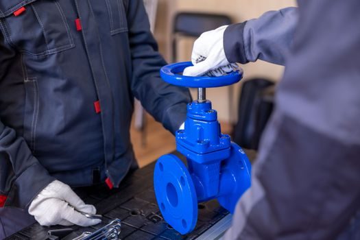
A standard conventional spring safety relief valve is the right call for clean service, set pressure below 90% of the test pressure, allowable built-up backpressure under 10% of set, and relieving temperature where PTFE or Stellite #6 trim is rated, which covers the bulk of HVAC, refrigeration, low-pressure steam, and compressed-air duties [S1].
It is the wrong call for viscous or polymerising fluids (plug a rupture disc plus SRV stack instead); for two-phase flashing service or high-viscosity relief (use a separate two-phase calculation and consider a balanced-bellows or modulating pilot design); for service where the discharge goes to a closed header with backpressure above 30% of set (use balanced-bellows or pilot-operated); and for any cryogenic or low-temperature chemical below -50 °C where PTFE becomes brittle (use PCTFE or metal-to-metal trim) [S2]. A buyer who tries to push a standard spring SRV into one of these services gets a working valve on day one and a documented NDT finding on the next inspection cycle.
Sourcing and Spec Discipline
The minimum datasheet a procurement engineer should require on a 2026 SRV RFQ: full model code, orifice letter, set pressure, relieving capacity in kg/h at the relieving pressure, body and trim material with ASTM/UNS reference, seat material with temperature limit, inlet/outlet size and connection type, UV/NB serial, capacity curve per API 520 part II, and the applicable code references (ASME BPVC Section VIII, ASHRAE 15, IIAR, PED, ATEX) printed on the quote rather than attached as a generic catalogue [S1].
When the same RFQ is run against 3-5 suppliers, the shortlist filter that actually separates OEM quality from catalogue resellers is whether the manufacturer publishes a serial-numbered capacity curve, not just a maximum-capacity number, and whether the trim is documented down to spring alloy and seat polymer. Track the next procurement cycle against the next update of API 520 part II and the next revision of the plant's PED conformity assessment; these are the two documents that routinely shift a previously compliant quote into a re-spec.
Detailed specification references: safety relief valve, linear guide, and crossed roller guide.