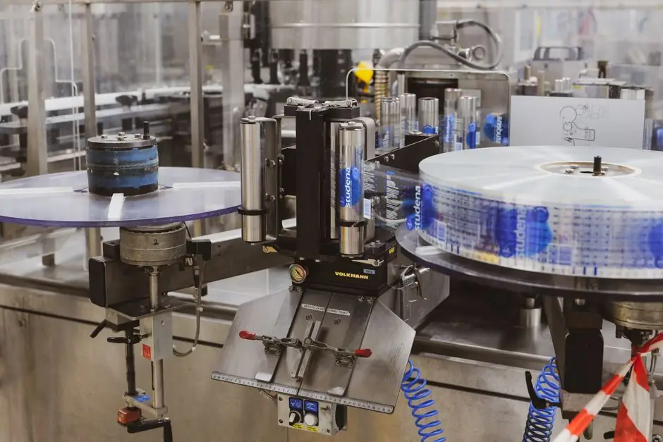
A packaging-line belt tensioner should hold the specified belt tension while accommodating shaft movement and packaging-process variation, rather than depending on periodic manual adjustment.
The correct choice depends on belt geometry, pulley arrangement, peak torque, contamination exposure, and the need for automatic take-up; the resulting drive must preserve alignment, tracking, and belt life.
Define the drive and tensioner duty before selecting hardware
A belt drive transmits power between shafts with an elastic belt and pulleys, and it may operate as a friction drive or as a positive drive [S4]. Packaging applications typically use compact open or multi-pulley arrangements, where an idler can increase wrap angle and maintain recommended belt tension [S4]. This makes the tensioner part of the drive geometry, not an accessory to add after the shafts are fixed.
Record motor power, motor speed, driven-pulley diameter, center distance, pulley widths, belt profile, operating hours, and the range of shaft movement. Confirm whether the drive handles cartons, film rolls, or other intermittent loads, and whether it runs continuously.
Use the selected belt manufacturer’s installation data to establish the required installation tension and the permitted tension range. Do not substitute a generic tension value for a belt-specific requirement. For a drive subject to shock loading, packaging jams, or frequent acceleration, size the tensioner and drive components for peak rather than nominal load.
Compare friction, synchronous, and flat-belt tensioning options
The belt architecture determines whether the tensioner must prevent slip or preserve positional tooth engagement. A frictional V-belt depends on adequate tangential force and wrap angle, while a timing belt is a positive drive whose tension maintains tooth engagement rather than frictional traction [S1][S4]. A flat belt remains applicable to older or special layouts, but its broad contact surface and tracking requirements demand careful pulley alignment and sufficient tension.
This comparison is a selection screen, not a complete drive calculation. Synchronous systems offer positive transmission, whereas friction drives rely on tension and pulley contact; incorrect comparison of those principles can produce either belt slip or tooth jump. Detailed synchronous-belt failure modes include wear, contamination, tension errors, and pulley problems, all of which must be checked during maintenance [S1].
Choose automatic take-up only after comparing spring and hydraulic mechanisms
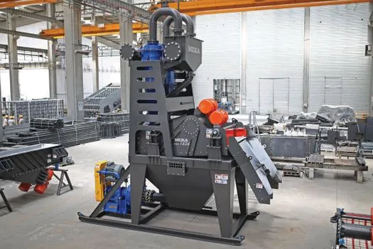
A jack-screw tensioner offers low cost, has the least number of components, and uses simple, readily available components [S5]. It is appropriate when shaft positions are fixed and belt wear changes do not materially alter alignment. It is not the first choice for an unattended line where tension must remain stable through temperature changes, product-load variation, and progressive belt stretch.
A spring tensioner applies force as belt length changes and is usually favored for low-maintenance operation because it removes routine manual retensioning. Position it on the slack side where practical, provide a defined adjustment range, and ensure the spring force remains within the belt manufacturer’s allowable range. SDP/SI offers belt tensioners and adjustment tools specifically to maintain system performance, confirming that take-up hardware is an established part of belt-drive design [S2].
A hydraulic or hydraulic-damped tensioner is appropriate where large static movement, shock absorption, or controlled tension variation is required. The cylinder must be sized for the required force and travel, while damping must match the drive’s dynamics. For a conventional packaging drive with stable shafts and modest take-up travel, hydraulic equipment can add leakage points, controls, and maintenance burden without delivering a proportional maintenance benefit.
Comparison on four criteria is direct: a jack screw wins on initial cost and component simplicity; a spring unit wins on automatic tension control with fewer hydraulic components; a hydraulic unit offers controlled force and damping but demands greater inspection; and a manually adjustable idler wins only where installation geometry is stable and planned adjustments are acceptable.
Match tensioner travel to belt wear and alignment risk
Symptom: a drive develops intermittent noise, slip, edge wear, or rapid tension loss. Root cause: the tensioner has exhausted its travel, its spring has weakened, or the moving idler has pulled the belt laterally. Corrective action: inspect the tensioner at its present position, compare it with the specified installation setting, and determine whether the required correction remains inside the adjustment range [S3].
Symptom: the belt repeatedly leaves its pulley groove or runs against one edge. Root cause: a plain idler or tensioner pulley is not tracking the belt, or shaft movement is introducing angular and parallel misalignment. Corrective action: use a flanged or crowned pulley where required and correct the pulley alignment. Crowned pulleys can improve belt tracking, while excessive misalignment causes improper tracking, uneven pulley wear, noise, and belt-edge wear [S4].
Symptom: a synchronous drive develops tooth skipping or abrupt vibration. Root cause: tension is outside the belt’s permitted range, the pulley is axially displaced, or the belt lacks sufficient engagement. Corrective action: verify tooth engagement, pulley location, belt tension, and alignment before increasing tension. Replace the belt or pulley when wear or damage has consumed the available adjustment range; do not compensate for a damaged component with excess spring force.
Symptom: a tensioner remains at one end of its travel soon after installation. Root cause: the initial length, center distance, idler position, or belt length is incorrect. Corrective action: verify the installed belt length and set the tensioner near the middle of its usable travel, leaving equal adjustment range for wear and settling. This practice is consistent with the Gates preventive-maintenance requirement to install the correct belt and properly install the drive [S3].
Control contamination, heat, and inspection frequency
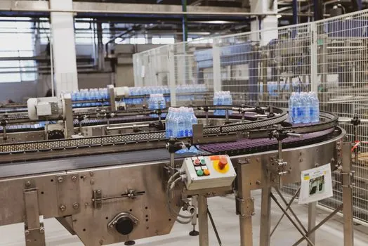
A low-maintenance tensioner is not a maintenance-free installation. Gates presents preventive inspection, maintenance, and replacement as the basis for reducing unplanned belt-drive downtime, and its manual covers V-belt and synchronous-belt sections, belt-length conversion, installation, and safety [S3]. Package-handling environments expose belts to paper dust, cardboard fragments, oil, and washdown residues, which can shorten service life even when the tensioner mechanism itself is sound [S1].
Establish acceptance criteria for inspection: a properly aligned pulley should not run laterally against the belt; the belt should sit within its usable width; the tensioner should not be at an adjustment stop; and visible cracking, fraying, glazing, contamination, or tooth damage should trigger investigation. The Gates manual identifies belt identification and correct installation as core maintenance controls, while its preventive program includes safe inspection and maintenance [S3].
For a polyurethane synchronous belt with a carbon tensile cord, the Gates manual identifies the product as suitable for high-torque, low-speed drives [S3]. This is a product-specific capability, not a blanket approval for every packaging application. Verify the exact belt grade, pulley profile, rated load, and operating conditions before using that design envelope.
Do not repair a tensioner with misaligned shafts, damaged bearings, cracked pulley rims, or a belt whose wear exceeds the permitted condition. Escalate replacement of the tensioner assembly when correct alignment cannot be maintained, when required travel exceeds the mechanism’s range, or when the belt’s installation tension is inconsistent across multiple adjustment attempts.
Specify the tensioner as an engineered component
A procurement specification should identify the belt type, pulley outside and inside diameters, groove or tooth profile, belt width, and installed center distance. It should also state the belt model and size, required installation tension or torque, minimum pulley diameters, wrap-angle requirements, permissible alignment, idler surface treatment, bearing bore, shaft diameter, adjustment range, and installation orientation. Gates documentation demonstrates that belt sections, nominal dimensions, length conversion, and preventive maintenance form part of a controlled drive specification [S3].
For a friction drive, the design guide treats drive-side tension, slack-side tension, and a constant wedging design factor as part of belt-drive design, so the tensioner must be checked against the complete load calculation rather than against motor power alone [S1]. For a synchronous drive, verify pulley tooth compatibility and the manufacturer’s tension limits. Gates lists synchronous belts, tensioners, pulleys, and complete drive systems as an integrated product family, supporting a system-level rather than loose-parts approach [S3].
Require commissioning records to include installed tension or spring setting, idler position, pulley alignment, run-up result, and thermal condition. The field adjustment choice must also be reflected in Specify Tensioner Pulley Bore and Bearing Seal Type, because bearing and seal requirements depend on the packaging environment rather than on the tensioner brand alone.
Start with a manual jack-screw arrangement only if planned retensioning is acceptable. For an unattended packaging line, use an automatic spring tensioner for stable, modest travel; specify hydraulic tensioning only when controlled damping or large force variation is justified by the drive calculation. Base final acceptance on belt-specific tension, pulley compatibility, alignment, and a documented preventive inspection interval.