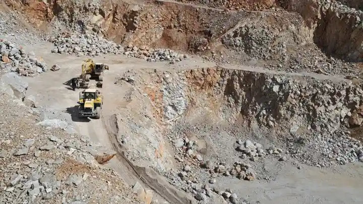
Mining steam-trap selection starts with five measured inputs: inlet pressure, back pressure, differential pressure, condensate load, and air-venting duty.
The resulting model must also match the application, body material, orientation, connection method, and condensate-return arrangement, because a correctly sized trap can still fail in a poorly designed system.
Establish the Steam-Trap Duty Before Comparing Types
A steam trap must discharge condensate and non-condensable gases while holding back live steam, so no single technology suits every mining duty [S2]. The selection process separates application requirements from model limits: determine whether discharge must be hot or subcooled, select a matching operating principle, calculate the load, and apply the manufacturer’s recommended sizing margin [S3].
For process-equipment condensate load, Emerson provides the rule “Condensate Flow Rate lb/hr = BTU Rating (in millions) / 100” when measured flow is unavailable [S1]. For heated equipment, continuous discharge is preferred because pooled condensate reduces heat transfer and can produce uneven heating [S3]. Tracer-line duty requires different treatment because the piping and heated-fluid temperature can be below 100 °C [S3].
Do not use inlet pipe size as the trap selection. The relevant drainage line is the equipment outlet feeding the trap, and the trap must not be smaller than that outlet because restriction can cause waterlogging [S5].
Compare the Main Trap Technologies by Duty
The selection guide lists float-and-thermostatic, thermodynamic lever, thermodynamic disc, thermodynamic piston, thermostatic bellows, thermostatic bimetalic, and inverted-bucket trap technologies alongside steam-trap applications [S1].
Float-and-thermostatic traps use a float to match the condensate level and provide continuous discharge. This family fits equipment drainage where continuous removal and air venting matter.
Thermodynamic disc traps are compact and suited to light or intermittent loads such as tracing and steam-main drainage. Their operation depends on the pressure and degree of superheat, a limitation that becomes important where pressure is reduced or condensate load changes [S1]. Armstrong specifically warns that thermodynamic disc traps are often assigned to duties for which they are not suited [S7].
Thermostatic and bimetalic designs are available for applications requiring temperature-responsive discharge, while inverted-bucket and lever mechanisms address other distribution and equipment duties [S1]. The correct comparison is therefore not “best trap,” but hot versus subcooled discharge, minimum differential pressure, load variation, air removal, installation orientation, and maintenance access.
Size for the Worst-Case Pressure and Condensate Load
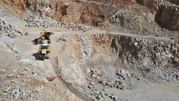
A mining trap must discharge its maximum calculated condensate load at the minimum differential pressure, including startup conditions and environmental effects [S5]. Inlet pressure, outlet or back pressure, differential pressure, and condensate flow are mandatory sizing inputs [S1].
These values are model limits, not proof that either model fits a given mine. The selected capacity must exceed the calculated duty at the available pressure differential without creating an oversized trap that remains closed or leaks during low load.
Where the steam-main condensate load is unknown, the insulation condition and ambient temperature must be known. In an exposed mine steam line, this adjustment can materially change trap capacity.
Condensate-return pipe sizing provides a second check. One general reference gives 1/2 in below 400 lb/h, 3/4 in at 400–1,100 lb/h, 1 in at 0.5–1 t/h, 1-1/4 in at 1–2 t/h, 1-1/2 in at 2–3 t/h, 2 in at 3–5 t/h, and 2-1/2 to 4 in above 5 t/h [S5]. Verify the applicable mine piping code and the actual return-line pressure before release.
Set Materials and Connections for Mining Conditions
Trap body material must be selected from the maximum pressure and temperature at the condensate-discharge location, the surrounding environment, and service-life requirements [S5]. Material choices include gray cast iron, ductile iron, carbon steel, and stainless steel [S5].
The body rating does not establish the complete trap rating. Gaskets, internals, covers, and other pressure-resistant components may impose lower pressure or temperature limits than the body [S5]. Body material must also satisfy the pressure-test and maximum pressure-temperature design specifications of the piping system [S5].
Stainless steel is a practical consideration where exposure, maintenance interval, or corrosion resistance supports its higher lifecycle cost. Treat these as body-material comparison values, not automatic trap pressure ratings, and verify the governing code and product bulletin.
Connections must match the mine piping specification and pressure class. Common options are threaded, socket-welded, and flanged [S5]. A threaded trap can reduce installation cost, but replacement requires disconnecting the outlet pipe or arranging a union; flanged service improves access at the cost of greater installed envelope and weight. Mining installations should also account for vibration, freezing exposure, dust, washdown, and mechanical damage when choosing the installation arrangement.
Avoid the Mainstream Trap Where the Layout Prevents Drainage
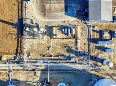
A conventional gravity-discharge trap should not be selected when the trap outlet has a lift to a pressurized return, because condensate must rise and the resulting installation has a persistent waterhammer risk [S2]. Spirax Sarco recommends supplementing the trap with a pump or using a pump-trap arrangement where condensate must lift [S2].
This is a common mistake in remote mining installations, where a trap may be buried in a trench, fed from a high process skid, or piped back to a condensate header at higher pressure. The failure is hydraulic, not simply a trap-model issue. Temperature-controlled heat exchangers with lift after the trap also face this constraint [S2].
Waterhammer can also result from condensate remaining in high-velocity steam lines, flooding or overpressurization in an undersized return, or flash steam produced by throttling [S2]. Repeatedly replacing a failed trap without correcting the piping layout wastes maintenance effort and shortens equipment life.
Design Steam Mains, Air Venting, and Condensate Removal as a System
Steam mains should be drained at intervals of 30–50 m with adequately sized drain pockets, and the bottom of every riser must be drained [S2]. A trap protects equipment only when the installation allows condensate to reach and leave it without restriction.
Air venting is a separate selection criterion. Equipment such as air heaters may retain startup air, and traps used for heated equipment commonly need an air-venting function [S3]. If a modulating steam valve reduces delivery pressure below the return backpressure, condensate flow can stall; the stated remedy is a higher-secondary-pressure pump-and-trap combination [S3]. A conventional trap is not an adequate substitute for a purpose-designed condensate-discharge system in that condition.
Dirt also affects selection because steam can carry traces of boiler-feed-treatment products and process contamination [S2]. For critical lines, inspect the internal mechanism, check whether the model is repairable, and confirm replacement availability before procurement. Emerson identifies FIT100 and FIT200 as repairable models, with NPS sizes including 1/2, 3/4, 1, 1-1/2, and 2 in and threaded, socket-weld, or flanged connections according to model [S1].
Mine Applications, Procurement Checks, and Acceptance Tests
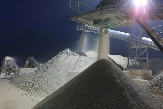
Steam-trap selection in mining covers steam-distribution mains, pressure-reduction stations, end-of-line drainage, tracer lines, process heaters, dryers, freeze-protection systems, and equipment such as autoclaves [S1]. Critical services need reliable air removal, continuous condensate discharge, and maintainable hardware; non-critical tracing can tolerate a different technology if its load and pressure are verified.
Emerson gives rule-of-thumb tracing loads of 60 lb/h for instrument tracing and 100 lb/h for line tracing [S1]. These are initial estimates only. Confirm them against the actual trap application because condenser load varies with heat input, pressure, insulation, start-up duration, and whether the line operates continuously or intermittently.
Before approval, record inlet pressure, back pressure, differential pressure, calculated condensate rate, maximum and minimum temperature, trap orientation, body material, connection type, capacity at minimum differential pressure, air-venting requirement, repairability, and installation accessories. Confirm that the trap can be isolated without draining a critical steam header or dismantling inaccessible piping.
Where the steam system also includes condensate separation, the sizing and installation requirements for a float steam trap paired with a condensate separator should be reviewed together rather than treated as independent component selections.
At commissioning, verify that the trap discharges condensate without passing live steam, that the return line is not flooded, that risers and drain pockets are accessible, and that the installed model matches the approved pressure-temperature envelope.