Pneumatic bulk tanker unloading typically starts with 0.15–0.25 MPa, equivalent to 22–36 psi, in the tanker vessel [S6].
The operating envelope spans roughly 1.5–2.5 bar gauge, but the correct pressure depends on material, pipe resistance, and the receiving silo [S5][S6].
Pressure Range for Pneumatic Tanker Unloading
Internal tanker pressure of 0.15–0.25 MPa is a practical starting range for pneumatic tank-truck unloading [S6]. This equals 1.5–2.5 bar and approximately 22–36 psi, giving the project team a usable initial design band rather than a universal setpoint [S6].
Road silo tankers commonly carry about 30 m³, sometimes more, and pneumatic discharge moves flour, sugar, chemicals, or plastics into a silo [S5]. A 30 m³ load of sugar represents approximately 960 bags of 25–50 kg or 30 Supersacks, reducing manual handling compared with packaged delivery [S5].
Pressure is not the only controlled variable. The valve manifold must balance tank pressure, fluidization at the discharge cone, air flow through the conveying pipe, and product admission to the line [S5]. Automated controls can reduce manual intervention, while complete system integration remains part of mobile bulk-unloading configurations [S2].
How the Unloading Pressure Produces Conveying
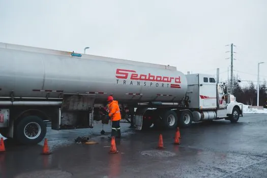
Truck unloading uses an onboard or stationary compressor to pressurize the tanker and push material through a pipeline into a silo [S3]. The tank pressure supplies the driving force, while the conveying line develops an additional pressure drop as material moves through the pipe [S5].
Older pneumatic-handling material identifies tank pressure and unloading rate as primary operating parameters and states that unloading pressure and rate can be recorded electronically [S4]. This makes pressure history useful for distinguishing a stable unloading curve from a line that is choking, starved of air, or losing flow as product accumulates in the receiver.
A tanker-mounted blower can provide the autonomy needed at a receiving site. The design example uses a diesel-powered reciprocating compressor with typical capacity of 12 m³/min and maximum pressure of 2 bar gauge [S5]. The pneumatic conveying blower sizing decision must therefore be checked against both free-air demand and pressure loss across the complete unloading route.
Select the Pressure by Material and System Type
A 0.15–0.25 MPa initial range is appropriate for screening, but it is not a universal operating requirement [S6]. Some road-tanker discharge arrangements can reach 1.5–2 bar gauge, which is acceptable while material continues to flow through the pipe and maintains the expected pressure drop [S5].
The comparison is straightforward: a low setpoint reduces vessel stress and compressed-air demand but may not move dense or cohesive material; a higher setpoint increases available driving pressure but can raise energy use, dust generation, and equipment wear if the line does not need it. Positive-pressure lean-phase conveying operates above atmospheric pressure and is used for products such as wheat flour and sugar [S7].
Option A, onboard tanker unloading, suits deliveries where the compressor travels with the vehicle. Option B, stationary unloading, suits sites that require a fixed receiving point and integrated controls [S2][S3]. Option C, manual valve operation, requires a trained operator, a written procedure, and disciplined valve sequencing because incorrect manipulation can cause pipe blockage or damage to the receiving silo [S5].
Match the Pressure to Material and Route
Pneumatic unloading must move the product quickly enough to empty the tanker efficiently and deliver it to the silo [S5]. Material characteristics determine whether 0.15–0.25 MPa is adequate, while pipeline length, bends, fittings, elevation, and receiver geometry add resistance that must be accounted for in the blower duty [S5].
Granular sugar can be handled by a conventional 30 m³ road silo tanker, and a 0.30 m³ capacity is typical for small bags while 1–2 m³ is common for big bags [S5]. Flour and sugar are also identified as positive-pressure lean-phase applications [S7]. Dense-phase systems remain a separate option, with Gericke listing both dense-phase and dilute-phase pneumatic conveying, vacuum conveying, diverter valves, and a GUC-C pneumatic conveyor controller [S2].
The practical selection rule is to start with the material supplier’s validated operating range, then verify that the compressor can maintain the required pressure at the measured flow rate. If the product bridges at the discharge cone, the problem may require aeration, outlet redesign, or a different conveying phase rather than simply more pressure [S4].
Controls, Safety, and Failure Modes
Electronic recording of unloading pressure and rate can provide visibility into the pneumatic unloading process, while factors such as changing unloading-circuit conditions may affect the process [S4]. The operating sequence must be treated as a controlled procedure because the manifold has to manage three separate functions: silo-tank pressurization, discharge-cone fluidization, and conveying-pipe air supply [S5].
Ground the truck to prevent hazardous static-electricity buildup [S5]. If the conveying gas is nitrogen rather than air, perform a site-specific risk assessment for asphyxiation and other additional hazards [S5]. The grounding requirement and gas-specific review apply at the unloading interface, where the receiving silo and vehicle become part of one connected system.
Common failure modes are pipe blockage, product damage at the receiving silo, unstable flow from incorrect valve operation, and excessive pressure after material flow stops [S5]. A line full of product can support the intended pressure drop, but the same pressure becomes a hazard when conveying stops and the line remains charged [S5]. Sequence shutdown so that air and product are isolated before a blocked or empty line remains exposed to vessel pressure.
Specify the Unloading Package Before Setting Pressure
A complete pneumatic unloading package can combine the truck or stationary compressor, tanker interface, conveying pipe, receiver, controls, and dust-management equipment [S1][S2]. HaF separately identifies vacuum dilute phase, vacuum dense phase, pressure dilute phase, pressure dense phase, and truck and railcar unloading as distinct pneumatic-conveying configurations [S1].
Specify the pressure band, expected unloading rate, compressor flow in m³/min, maximum working pressure in bar gauge, pipe route, material bulk density, and receiver capacity before assigning a final unloading setpoint [S5][S6]. A conventional road-tanker blower example is 12 m³/min at up to 2 bar gauge, but that equipment should be matched to the line rather than used as a universal specification [S5].
Track the pressure-versus-time trace at startup, steady conveying, and shutdown. A sustained pressure increase with falling mass flow identifies restriction or receiver loading, while pressure below the validated range indicates insufficient compressor performance, valve imbalance, air leakage, or a starved material feed. This operating trace is the most useful next node for confirming whether the selected 0.15–0.25 MPa range is suitable for the installed material and route [S6].