
A degassing unit must be sized against the volume of metal treated, while its rotor speed must be raised as gas flow increases to disperse the larger gas volume into fine bubbles.
For aluminum melts, a fixed gas-flow number is not a production specification: the relevant variables are treated melt volume, treatment time, injector geometry, rotor RPM, and the hydrogen-removal target.
Degassing gas flow is not a standalone capacity rating
A gas flow rate in m³/h describes the volumetric gas supply, not the mass or volume of metal that can be degassed to a specified level. The actual treatment capacity depends on how the gas is introduced and dispersed through the melt, not on the meter reading alone. [S4]
For aluminum, increasing gas flow increases the gas volume that the rotor must distribute. Higher flow rates require slightly higher RPM to shear that increased gas volume into fine bubbles effectively [S9]. This interaction means that a degassing unit selected only from its nominal gas-flow rating may underperform when the melt batch, treatment time, or transfer configuration changes.
Two separate capacity checks are therefore required. First, calculate the melt batch volume and confirm that the permitted treatment time can accommodate that batch. Second, confirm that the injector, rotary tool, shaft, and motor can operate at the gas flow and RPM needed to distribute the bubbles. A large furnace does not automatically require a large degassing unit if the melt is treated in smaller portions, but a large single batch does require a verified treatment cycle.
Use the MFR and MVR distinction for process comparison
Melt mass-flow rate, MFR, is reported in g/10 min, while melt volume-flow rate, MVR, is reported in cm³/10 min; the quotient of MFR and MVR gives the melt density used for conversion under ISO 1133-1 and ASTM D1238 [S1]. This distinction is useful when comparing polymer processing data, but it is not a direct formula for aluminum degassing capacity.
The mass-based and volume-based methods are technically related but answer different questions. MFR describes the mass of thermoplastic material passing through a standardized die in 10 minutes, whereas MVR describes the corresponding volume [S1][S2][S3]. MVR is often more stable for filled or density-variable polymers, while MFR remains more familiar for incoming material control [S3].
This provides a useful analogy for melt-processing equipment: do not compare a mass-based output with a volume-based requirement without conversion. For degassing, the equivalent discipline is to use melt volume as the denominator and to keep gas flow, treatment duration, and bubble dispersion linked. The calculation should not be transferred blindly to polymers because aluminum density, viscosity, gas solubility, and rotary-shear behavior define a different process.
Compare rotary and spray degassing by dispersion and throughput

Rotary degassing creates fine bubbles by introducing gas through a rotating disperser, while spray degassing relies on atomized melt droplets with a very large surface-to-volume ratio. In spray degassing, hydrogen in atomized melt droplets can be removed readily because the gas contacts the droplet surface [S8].
Against three criteria, the two methods separate clearly. Rotary systems emphasize controlled bubble dispersion and offer a direct relationship between RPM and gas distribution [S9]. Spray systems emphasize melt surface area and droplet transfer, with the 2005 analysis identifying the large surface-to-volume ratio as central to hydrogen removal [S8]. For capital footprint, neither method can be ranked from the supplied evidence because no equipment-cost or installation-cost data are given.
For an existing rotary installation, preserve the operating envelope established for its injector and rotor rather than increasing gas flow without checking RPM. For spray systems, evaluate how the melt is transferred, fragmented, and exposed to gas. The method selection should be based on measured hydrogen removal, cycle time, melt loss, and treatment uniformity, not on nominal gas consumption alone.
When comparing rotary impeller and diffuser arrangements, gas diffuser vs rotary impeller for aluminum degassing provides the relevant distinction between gas-entry hardware and the method that actively disperses gas through the melt.
Specify gas flow per batch, not per furnace
A defensible gas-flow specification starts with the actual melt batch volume in liters or cubic meters, the required treatment time, and the verified gas-to-melt distribution for the chosen rotor and injector. The required result is a repeatable process window expressed in m³/h, minutes, and RPM, with the melt batch size recorded beside it. [S3]
For example, if one aluminum batch contains 2.0 m³ and the planned cycle is 10 minutes, the average gas volume introduced during that cycle must be reconciled with the unit's m³/h rating. The arithmetic does not establish hydrogen removal efficiency, so the qualified operating point still needs test data for the melt temperature, alloy, rotor design, and injector condition.
The same calculation becomes a different specification when the batch is divided into two 1.0 m³ portions. More frequent treatment can reduce the volume handled per cycle, but it also changes total cycle time, laadle handling, heat loss, and exposure to atmosphere. The equipment should be sized around the largest accepted batch and the production schedule, while the casting ladle specification should preserve enough working capacity to transfer that batch without an avoidable process constraint.
Match the degassing unit to the melt-production route
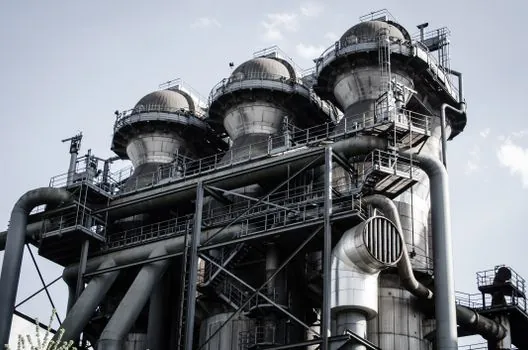
Continuously melted production and batch treatment impose different constraints. A gas-aluminum melting furnace feeding a holding or transfer stage may support a repeatable rotary treatment point, but the required gas flow must still be reconciled with the volume entering treatment during the specified cycle. [S1]
For a crucible furnace, melt is generally handled in smaller increments than in a large production furnace, so the degassing calculation must follow the actual transfer quantity rather than furnace nameplate capacity. For a cupola furnace, production rate, tapping interval, and the portion of tapped metal routed through degassing determine the effective gas demand.
That distinction prevents a common sizing error: using total furnace capacity as though every cubic meter were degassed in one simultaneous batch. The correct basis is the maximum qualifying melt volume presented to the degassing unit in one cycle. The comparison criteria are treatment volume per cycle, elapsed cycle time, required RPM at selected gas flow, and verified hydrogen removal.
Control the variables that distort comparison
Melt temperature, alloy, hydrogen level, rotor condition, injector immersion, treatment time, and gas purity can change degassing performance independently of the meter reading. The 2026 aluminum analysis identifies the RPM and flow-rate interaction as a central operating issue: adding gas without increasing RPM can leave a larger gas volume insufficiently dispersed [S9].
For polymers used as a comparison material, moisture, filler content, glass-fiber content, carbon-fiber content, and operator technique can alter MFR or MVR results [S4]. That finding reinforces the need for controlled test conditions rather than a direct transfer of a material rate into a metal-treatment calculation.
Instrument verification should cover at least three measurable points: the calibrated gas flow in m³/h, elapsed treatment time in minutes, and the melt volume in the vessel. Process records should also retain rotor RPM, melt temperature, alloy, initial hydrogen level, final hydrogen level, and any sampling delay. The ISO 1133-1 and ASTM D1238 methods apply to thermoplastic melt-flow testing, not aluminum hydrogen analysis, so they must not be cited as the governing test for furnace degassing [S1].
Verify performance with hydrogen measurements

Gas flow per melt volume is a sizing variable, while hydrogen removal is the acceptance result. A qualified operating point should connect gas flow in m³/h, batch volume in m³, treatment time in minutes, and RPM to measured hydrogen in the melt before and after treatment. A unit that meets flow demand but misses the hydrogen target is oversized on paper and underperforming in service. [S3]
Trackable commissioning signals are the validated maximum batch volume, the stable RPM-to-gas-flow map at production temperature, and repeatability of final hydrogen results across at least three treated batches. If gas consumption rises without a corresponding improvement in hydrogen removal, investigate bubble dispersion, injector condition, melt temperature, and treatment time before increasing flow further. This is the practical decision rule: size flow for the accepted batch, match RPM for dispersion, and approve the combination against measured hydrogen reduction.