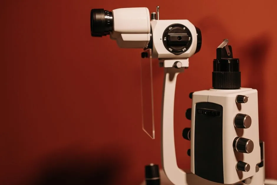
A shadowgraph comparator and a standard optical comparator (also called a profile projector) are both non-contact 2D inspection tools, but they differ in optical path, magnification discipline, screen geometry, and best-fit workpiece [S3][S4].
Both use transmitted light and a viewing screen, both trace back to the Hartness screw-thread comparator introduced in the early 20th century, and both remain common in machine shops because the shadow is fast to read and never touches the work [S1][S3].
Light Path and Screen Geometry: Upright vs Folded
A shadowgraph uses a simple vertical light path: the lamp, the part on a glass stage, and the projection screen sit on a single optical axis, so the shadow you see on the screen is the same orientation as the part on the stage [S4].
A standard optical comparator adds a telecentric projection lens plus one or more fold mirrors, which lets the cabinet be compact and, more importantly, keeps magnification fixed even if the part drifts slightly in Z away from the lens [S4]. Both styles typically cast a sharp enlarged silhouette on a ground-glass screen carrying a cross-hair reticle and an angular protractor grid [S3][S4].
Magnification, Accuracy, and What You Can Read
Standard optical comparators are sold with interchangeable lens magnifications commonly in the 10x, 20x, 50x, and 100x range, with some benches going higher; the screen shadow size equals the real feature size times the lens factor [S2][S4].
Calibrated positioning accuracy on a modern optical comparator is typically around 0.005 mm, and the measurement comes from stage travel under a digital readout, not from an operator judging distance on the screen, which removes the human-estimation error from the loop [S2][S4]. A shadowgraph bench, with its shorter optical path and usually lower fixed magnification, is best for larger parts and quick go/no-go overlay checks rather than tight tolerance work.
Configurations: Horizontal, Vertical, and Bench-Top
Optical comparators are sold in two main configurations: horizontal machines, which suit heavy, long, or cylindrical parts because the optical axis lies on its side and the part rests under gravity on V-blocks or fixtures, and vertical machines, which suit flat, flexible pieces such as rubber gaskets, stampings, and thin sheet components [S2][S5].
Most shadowgraph benches are vertical because the through-light path needs a translucent stage, and the part-screen orientation must stay upright so overlays can be pinned directly to the screen [S4]. The cross-hair and protractor reticle on the screen is usually rotatable through a full 360 degrees, which lets the operator align the shadow to a reference datum rather than rotating the part [S3].
What It Measures, and What It Cannot
An optical comparator measures anything that can be cast as a clean 2D outline: outside dimensions, angles, radii, thread pitch and form, gear tooth profiles, stamped and molded contours, drill point geometry, and the tip radius of a cutting insert [S3][S4][S5].
It does not measure 3D features, hidden internal features, or surface finish, and soft or squishable parts such as silicone O-rings and rubber gaskets are common applications precisely because nothing mechanical touches the work [S2][S4]. When a job needs 3D, datum-referenced GD&T, or full feature-of-size reporting, that work belongs on a coordinate measuring machine, not on a comparator bench [S1][S4].
Comparison Table: Shadowgraph vs Standard Optical Comparator
The four decision criteria that matter most on the shop floor: optical path, magnification, typical accuracy, and best-fit workpiece. [S4]
Optical path: shadowgraph uses a direct vertical beam with no fold mirror; standard optical comparator uses a telecentric lens plus fold mirrors, giving a compact cabinet and constant magnification even with small Z drift [S4].
Magnification: shadowgraph is usually low fixed, around 5x to 20x, suited to large parts; standard optical comparator accepts interchangeable lenses at 10x, 20x, 50x, 100x, and higher, with shop-floor units commonly 10x to 100x [S2][S4].
Typical accuracy: shadowgraph is suited to overlay comparison and quick dimensional checks; standard optical comparator with a calibrated stage delivers positioning accuracy around 0.005 mm [S2][S4].
Best-fit workpiece: shadowgraph handles larger flat parts, gaskets, and coarse profiles where reading a full silhouette matters more than sub-hundred-micron precision; standard optical comparator is the choice for small precision features such as threads, gear teeth, cutting tool tips, and stamped electronic contacts [S3][S4][S5].
How It Fits Beside Other Metrology Tools
On a typical inspection bench, the optical comparator sits between handheld gauges and a full CMM: calipers and micrometers read one dimension at a time, the comparator shows the whole 2D profile at once, and the optical comparator category as a whole fills the gap for fast, non-contact profile checks that do not need 3D datum reporting [S1][S4].
The same bench often pairs a comparator with a pressure transmitter on a calibration fixture, or with an optical glass reference standard for reticle verification, because the shadow you read is only as good as the lens and screen behind it [S4]. For plants already running digital twins off CMM data, an optical comparator still earns its place as a one-second go/no-go station on the line, while the CMM handles the slower, fully reported first-article inspection.
Practical Limits and What Breaks the Reading
Five things consistently degrade an optical comparator reading: a non-telecentric lens that lets magnification shift with part Z position, a dirty or scratched glass stage that adds stray edges to the shadow, ambient light leaking into the screen cabinet, a worn cross-hair reticle whose lines are no longer truly orthogonal, and an operator who tries to read small dimensions off the screen image instead of off the stage digital readout [S4].
For deeper coverage of how older comparator designs stack up against modern vision systems, the practical trade-off is that the comparator survives on the shop floor precisely because it has fewer parts, runs cooler, and tolerates vibration better than a digital camera-and-software bench, which is the same reason piezoelectric accelerometer calibration stations still trust the projector for first-article checks of accelerometer housings [S6][S9].
When a Shadowgraph Is the Right Call
Specify a shadowgraph when the part is large, the feature you are checking is bigger than roughly 1 mm, the tolerance is on the order of 0.02 mm or wider, and you primarily need to overlay a master chart against the live shadow to confirm a profile, for example gaskets, flat stampings, and formed sheet metal brackets [S4].
Specify a standard optical comparator when the feature is small (often well under 1 mm), the tolerance is in the 0.005 mm class, the operator needs to walk the stage under a digital readout, and the part profile is complex, such as threads, gear teeth, medical cutting tools, and electronics lead frames [S2][S4][S5]. In practice many shops keep both, with the shadowgraph on the receiving-inspection bench and the telecentric-lens comparator on the first-article and tool-room bench.
Trackable signals for the next buying cycle: whether your shop is moving first-article inspection fully onto CMM and vision systems, and whether the remaining comparator work is large-format overlay checks (a shadowgraph job) or tight-tolerance point-to-point measurement (a telecentric-lens optical comparator job), because that ratio decides which of the two benches to standardize on.