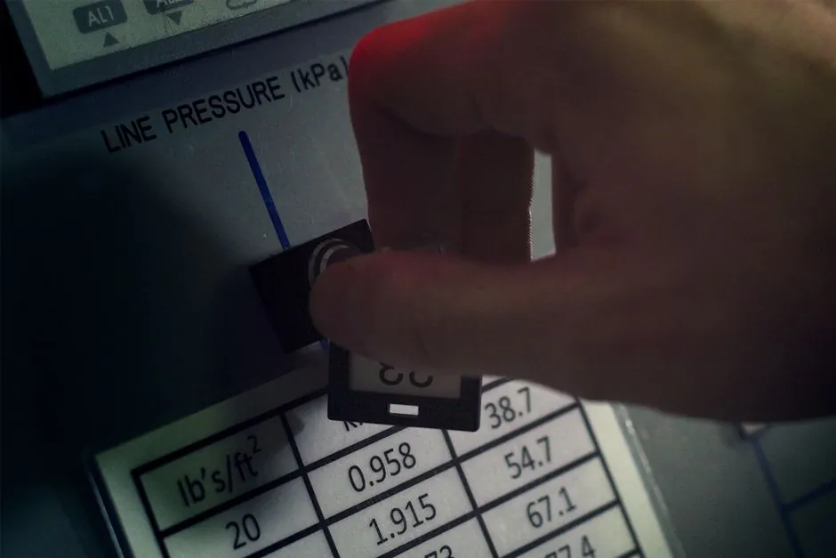
A modern multifunction process calibrator (for example the Fluke 726) exposes two independent electrical channels that can source and measure at the same time, so the technician can drive a 4-20 mA input into a transmitter while reading the 4-20 mA output on the second channel in real time [S4].
Source mode forces a known signal into a passive load, while measure mode reads whatever the device under test returns; when the calibrator's internal 24 V loop supply is enabled it powers a 2-wire transmitter on the bench, removing the need for an external power supply [S4]. Simulate mode is a third operating state in which the calibrator drops into the loop in place of a transmitter and passively regulates the current set by the external 24 V supply, useful for end-to-end loop checks without disturbing field wiring [S1][S5].
What "Two Channels at Once" Actually Means in Hardware
Inside the calibrator, the source channel and the measure channel are separate signal paths with their own DAC/ADC, sense resistors and protection, so sourcing 12.000 mA on channel A while measuring 11.972 mA on channel B does not load or distort either reading [S4]. On the Fluke 726 the DC current range covers 0-24 mA at 0.01 percent plus 2 µA accuracy, the DC voltage range covers 0-30 V at 0.01 percent plus 2 mV, resistance covers up to 4000 Ω, and frequency covers up to 15 kHz, with the same channel used for sourcing or measuring depending on the selected mode [S4]. Channel-to-channel isolation is what allows the 24 V internal loop supply to coexist with a 0-30 V measurement on the second channel without back-feeding the transmitter under test.
Source vs Simulate vs Measure: The Three Operating Modes
Source mode: the calibrator is an active current or voltage source, internally generating the signal. A 2-wire transmitter with no loop power is dead in this mode, so the technician must either power the transmitter separately or switch the calibrator into a mode that supplies loop power [S5]. Simulate mode: the calibrator is connected in place of a transmitter, the external 24 V (or 48 V) DCS supply is still in the loop, and the calibrator only regulates that current to the setpoint by sinking the appropriate amount, which lets the DCS see a real live current without the transmitter being installed [S1][S3]. Measure mode: the calibrator is a high-impedance meter in series with the loop (for current) or in parallel (for voltage), reading what the loop is actually doing without disturbing it [S2][S4]. A typical 4-20 mA loop check uses all three in one pass: simulate 4.000, 12.000 and 20.000 mA from the calibrator while the DCS or PLC trend records the returned indication, a job that the Fluke 725/726 can also auto-step through 0, 25, 50, 75 and 100 percent of span unattended [S4].
Why a Technician Cares: Reading the Output While Driving the Input
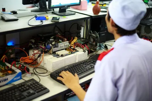
The defining field use of a two-channel calibrator is transmitter calibration: apply a calibrated input (pressure, temperature, RTD resistance, thermocouple millivolts) on channel A and read the resulting 4-20 mA output on channel B, then compute error against the ideal transfer function [S2][S4]. The same physical hookup is used for a valve positioner check, where the calibrator sources 4-20 mA to the positioner and reads back the mA or position feedback on the second channel [S4]. For a worked example, a 0-10 bar transmitter with applied 5 bar input should read 12.000 mA; if it reads 12.040 mA the error is 0.25 percent of span, and most modern multifunction calibrators compute and display this error percentage directly without a handheld calculator [S4]. This simultaneous source-and-read pattern is what distinguishes a multifunction process calibrator from a single-function loop calibrator, which usually forces the technician to flip leads or swap instruments mid-check.
Voltage, Resistance, Frequency and Temperature: The Same Pattern, Different Units
The same two-channel architecture works for every other signal type. For a thermocouple input the source channel outputs millivolts with cold-junction compensation, and J, K, T and E types are the most common in field work, while the measure channel reads either the loop mA output or a secondary TC reference [S4]. For an RTD input the source channel synthesizes the Pt100 (or Pt385, Pt3916, Cu, Ni) resistance curve, and the measure channel reads the resulting 4-20 mA; resistance output on the 726 reaches 4000 Ω, more than enough to cover a Pt1000 over its industrial range [S4]. For frequency and pulse the source channel drives 0.01 Hz to 15 kHz, and the second channel can be set to count returning pulses from a flow totalizer or to read a pulse train's frequency for verification [S2][S4]. Pressure is handled with an external smart module (the Fluke 750P series is the reference) that plugs into the calibrator's pressure port, and 0.025 percent of reading accuracy is achievable with the right module [S4].
Loop Power, HART, and What the Calibrator Will and Will Not Do
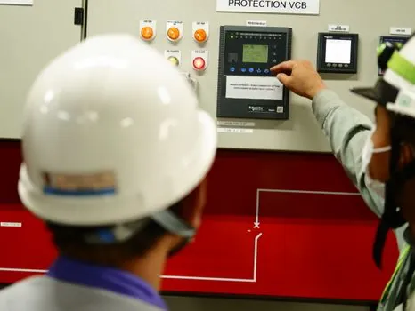
The internal 24 V loop supply on the Fluke 726 delivers up to approximately 22 mA, which is enough to power almost any 2-wire 4-20 mA transmitter on the bench, but it is not sized to drive a long field cable with multiple loads, so for in-place loop checks the technician still relies on the plant's existing 24 V or 48 V supply [S3][S4]. A practical limit documented for the older Fluke 707/705/715/789 family is that sourcing into an already-powered loop without entering simulate mode will fight the supply, hence the simulate-mode-as-passive-sink design [S3][S5]. For a loop tester the same dual-channel principle applies, but the focus is fault-finding rather than accuracy verification. Technicians who need to read HART variables alongside the analog 4-20 mA value should use a HART-enabled calibrator or clip a HART communicator across the loop, because a basic multifunction process calibrator reads only the analog current, not the digital HART data riding on top of it. If a separate transmitter excitation voltage is required, an accessory loop power distributor can be inserted to provide clean isolated 24 V to multiple loops from a single bulk supply.
Selection Criteria: Multifunction vs Single-Function vs Documenting
Choose a multifunction process calibrator when the technician needs to cover mA, V, RTD, TC, frequency and pressure in one handheld, which is the common case for plant maintenance crews [S2][S4]. Choose a dedicated loop calibrator (Fluke 707, 705, 715) when the only job is 4-20 mA sourcing/simulating and read, and a smaller, faster tool is preferred [S3]. Choose a documenting calibrator with on-board memory and PC software when ISO 17025 or similar quality-system traceability is required, because paper logging of every 0, 25, 50, 75, 100 percent step is impractical beyond a handful of transmitters [S4]. For a stationary panel or shop test bench a multifunction power meter or a bench-top calibrator with 0.005 percent DC accuracy may be more appropriate than a field handheld, because the field-grade 0.01 percent is usually dominated by sensor and not the calibrator. Auto step and auto ramp are the under-appreciated time savers: set 0-100 percent ramp on 4-20 mA, watch the DCS trend for linearity, and the technician is free to do valve and switch checks in parallel [S4].
Limits, Failure Modes, and What Trips Up a Good Calibrator
Excessive loop resistance is the classic failure: a 24 V supply can only push 20 mA through about 1200 Ω of total loop resistance (24 V minus the transmitter's 12 V drop, divided by 0.020 A), so a 250 Ω sense resistor plus 750 Ω of cable and barrier leaves no headroom and the calibrator's simulate mode saturates [S3]. Loop-powered isolators are even tighter: typical pickup voltage of 5.5-13.5 V on the input and a reduced 7.5 V compliance on the output, giving a total loop loading capability around 350 Ω, which is the primary limitation when verifying these devices [S3]. HART communication can be disturbed if the calibrator is inserted incorrectly in series, because HART expects a low-impedance path for its 1200/2200 Hz FSK signal and some early loop calibrators with current-limiting diodes would clip the HART waveform; modern calibrators are designed to be HART-transparent, but it should be confirmed before relying on a HART communicator downstream [S3][S4]. Pressure modules are the most fragile part of a multifunction calibrator: over-range to 1.5x the module's rated pressure, or sudden pressure spikes from a hand pump, are the most common field failure modes. Finally, RTD and TC sourcing accuracy depends on the cold-junction compensation, and a sudden ambient change of 10 °C can shift a Type K output by roughly 0.4 mV (about 0.1 °C equivalent at 0 °C reference), so for high-accuracy TC work the calibrator should be allowed to thermalise at the actual use temperature for several minutes.
Field Procedure: A 4-20 mA Loop Check in Five Steps
Step 1: confirm the loop power source is identified, whether it is the calibrator's internal 24 V supply (bench) or the plant DCS 24 V/48 V supply (field) [S3][S4]. Step 2: connect the source/measure leads to the appropriate terminals (mA, simulate, or measure), and on a Fluke 789 the leads go to the center or simulate terminals for the simulate procedure [S3]. Step 3: select 4-20 mA source mode and step through 4.000, 8.000, 12.000, 16.000, 20.000 mA, using the calibrator's auto-step if available, while the second channel reads the return [S4]. Step 4: record the as-found error at each of the five test points, compare against the allowable error (often 0.25 percent or 0.5 percent of span depending on the transmitter's criticality), and adjust zero and span if a calibratable transmitter. Step 5: for the as-left check, repeat the same five points and capture the error percentage for the calibration record, which on a documenting calibrator is stored on board for later upload [S4]. This same procedure applies to a vision light source calibration in a machine-vision cell, where the calibrator sources a reference voltage or current to the LED driver and the second channel reads the optical feedback sensor's 4-20 mA output.
How This Maps to Common Industrial Loops
A differential-pressure flow transmitter loop is calibrated by sourcing a differential pressure with a hand pump and a pressure module on channel A, then reading the 4-20 mA on channel B; the expected mA follows the square-root transfer function for flow, not a linear one, so 25 percent of DP span is 50 percent of flow output [S2][S4]. A thermocouple temperature loop is calibrated by sourcing a mV signal with cold-junction compensation on channel A (or measuring the TC head directly with a reference probe), and reading 4-20 mA on channel B; the error is computed against the TC tables for the chosen type [S2]. A valve positioner is checked by sourcing 4, 8, 12, 16, 20 mA on channel A and reading the position feedback (mA or V) on channel B; linearity, hysteresis and deadband are the three reported numbers [S4]. A pressure switch is tested by ramping pressure up and down through the setpoint with the pressure module, and the calibrator's switch-test mode captures the setpoint, reset point and deadband automatically [S4].
The underlying reason two channels can work in parallel is the calibrator's internal galvanic isolation between the source and measure paths, plus the design choice that the loop supply, sourcing, simulating and measuring are all time-multiplexed or fully paralleled on independent analog front ends, so no single test point has to be reconfigured by the technician. The next trackable signal for any user is the revision of IEC 61298 (process measurement transmitter evaluation) and the continued roll-out of HART-IP and Ethernet-APL two-wire digital loops, which will eventually move the source-and-read concept from a 4-20 mA bench to a fully digital asset-management workflow, but for the next several years the 4-20 mA + HART analog combination remains the dominant signal a field calibrator will be asked to source and read at the same time.
For related coverage, see Tall Wall Forms: When to Combine Internal and External Vibrators.