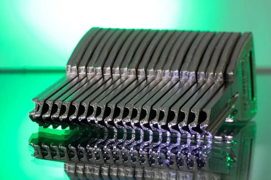
Parallel keys with square or rectangular cross-sections are the most widely used machine keys, and they dominate low-to-mid torque hubs in automotive powertrain and accessory drives [S1]. Rectangular-faced parallel keys are preferred once shaft diameter climbs past the size where a square section starts wasting keyway depth [S1].
Automotive line engineers treat the keyed joint as a three-piece system: shaft keyway, key, and hub keyseat, with torque carried by shear on the key sides and compression on the key top [S2]. The selection question is therefore not "which key?" but "which key geometry, length, and stock matches this shaft diameter, hub length, and torque reversal pattern?"
Key Types That Actually Show Up on an Automotive Line
Parallel, rectangular, and tapered keys remain the three most common profiles specified for shop-floor key stock [S2]. Sunk keys (Woodruff, Gib-head, feather, parallel sunk, square sunk, rectangular sunk) are used where a deeper key seat is acceptable in the shaft and the hub can be countersunk [S2].
Splines are described in published ISO, DIN, and ANSI standards with 4, 6, 10, or 16 teeth, and are described as the most common in automotive drive shafts where positive drive plus axial movement is required [S2]. Feather keys are used when a gear or coupling must slide along the shaft under load, with a closed shaft groove for the key when the key is shaft-fixed, or a double-headed key fixed to the hub when the hub must slide [S2]. Round keys and Woodruff keys are easy to manufacture because the keyways can be drilled and reamed after assembly of adjacent parts [S2].
Standards That Govern Key Dimensions and Tolerances
Key dimensions and tolerances are governed by BS 4235, ASME B17.1, and DIN 6892, with material selection layered on top by torque, corrosion, and compatibility requirements [S4]. Modern CNC and EDM processes let Woodruff and spline keys hold tight tolerances, which matters for automated assembly cells where vision systems check key-seat alignment [S4].
For an automotive engineer the practical reading is: pull the key-size table from BS 4235 or ASME B17.1 for the given shaft diameter, then verify the hub keyseat depth against the standard's tolerance band, and only then look at key stock grade. Published standards cover only key and keyway dimensions; they mostly do not discuss material, shape, or installation practice, which is where most shop-floor failures originate [S5].
Material Match Rule: Key Strength Has to Track Hub and Shaft
To avoid overload failures, the key material should match the strength and hardness of the shaft or hub, because key stress can run roughly 50% higher than shaft stress when the hub length is approximately equal to the shaft diameter (typical of modern alloy-steel couplings) [S5].
Key stress equals shaft stress only when the key (or hub) length is 1.6x the shaft diameter, a geometry older couplings sometimes met and modern hubs rarely do [S5]. Because part of the torque is carried by friction at the shaft-hub bore interface, the key stock does not need to be stronger than the shaft; it needs to be as strong, and key stock is available from most steel suppliers in carbon and alloy grades matched to common shaft steels [S5]. For deeper context on grade matching, see the related piece on Shaft Key Material Selection for High Torque: Grade Match Rules.
Fit and Geometry: The Four Conditions Most Specs Forget
A correctly fitted key satisfies four conditions: tight in the shaft keyway; sliding (not clearance) fit in the hub keyway; small radial clearance between the top of the key and the bottom of the hub keyway; and key length extending inward from the shaft end (never past it) to beyond the hub end by at least the key's rounded portion [S5].
Corners must be chamfered to clear the keyway fillet radii; an over-large chamfer shrinks the side contact area and makes the joint more vulnerable under shock load [S5]. A loose-fitting key lets torque forces roll the key, generating edge loading that shears the key [S5]. For coupling hubs the radial clearance doubles as a contamination path, so room-temperature vulcanizing (RTV) sealant is applied on top of the key before the hub is installed to keep water and corrosive gases out of the coupling internals [S5]. Parallel keys transmit unidirectional torque at low starting loads, and hubs are usually additionally secured with set screws when no axial hub movement is required [S2].
Comparison: Parallel vs Tapered vs Spline vs Feather
Selection on an automotive line can be reduced to four decision axes: torque reversals, axial hub movement, hub length vs shaft diameter, and assembly automation. [S2]
Parallel keys (square or rectangular) carry torque in one direction at low starting loads, accept periodic hub repositioning, and are the default for gear and pulley hubs that sit on standard BS 4235 / ASME B17.1 / DIN 6892 shafts [S2][S4]. Tapered keys (plain or Gib-head) lock the hub axially but require a precise drive-in depth; too far ruins hub-to-shaft contact, not far enough lets the hub slide, and there is no reliable in-line check for the right depth [S5]. Splines (4, 6, 10, or 16 teeth per ISO/DIN/ANSI) carry bidirectional torque and permit axial movement, which is why they are the default on automotive drive shafts and gearbox output shafts [S2]. Feather keys exist specifically for hubs that must slide along the shaft under load, with the key fixed either to the shaft (closed groove) or to the hub (double-headed) [S2].
Failure Modes and Limits Engineers Plan Around
The dominant failure modes are key shear from torque overload, key rolling from a loose fit, hammering on the key sides from micro-slip on torque reversal, and hub splitting from an over-tight hub fit [S5]. Sunk keys, including Woodruff and Gib-head, embed half their thickness in the shaft and countersink into the mating part, which deepens the effective keyway and reduces shaft section at that point, a real concern at small shaft diameters in transmission countershafts [S2].
Round keys are quick to manufacture and align because the keyways can be drilled and reamed after adjacent components are mounted, but their circular cross-section concentrates stress at the contact arcs and they are rarely specified for high-cycle automotive duty [S2]. For applications where repeated torque reversals and shock loads dominate, a shaft key made from a grade matched to the shaft material, with chamfered corners and a sliding hub fit, outperforms a generic mild-steel key on every meaningful metric.
Procurement and Line-Side Specifications
On a build sheet the key is normally called out as: standard (BS 4235 / ASME B17.1 / DIN 6892), cross-section (e.g. 10x8 mm rectangular), length (1.0x to 1.6x shaft diameter, with 1.6x the stress-matched case), material grade (matched to shaft material, often medium-carbon or alloy steel key stock), chamfer (small, per standard fillet clearance), and fit class (tight on shaft, sliding in hub, radial clearance at hub keyway top) [S4][S5].
For splines, add tooth count (4, 6, 10, or 16), pressure angle, and the relevant ISO/DIN/ANSI standard so the mating part supplier matches the same spec [S2]. Two trackable signals to watch on the next spec revision cycle: (1) any tightening of fit-class language in BS 4235 or ASME B17.1 to address hammering failures seen in modern short-hub couplings, and (2) wider use of involute splines over rectangular parallel keys in EV reducer output shafts as torque density climbs.