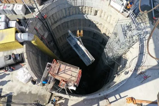
During construction, the trench is supported with slurry, while anchors may be used to increase the load-supporting capacity of a completed diaphragm wall.
The governing demand depends on the suspended grab mass, digging resistance, crane configuration, roller spacing, guide-wall geometry and the permissible movement of the rig.
Guide-Wall Reaction Load Path
A trench cutter or diaphragm wall grab excavates the trench, and guide walls maintain horizontal alignment. A suspended hydraulic grab removes soil in open-close cycles under stabilizing slurry; after excavation, joint elements and the reinforcement cage are inserted and the trench is concreted [S1][S7].
Guide walls are constructed in-situ, typically as lightly reinforced concrete elements, to maintain horizontal alignment. The cited sources establish that guide walls maintain horizontal alignment but do not establish that they restrain lateral rig movement or define panel geometry.
Four Reaction Components
Overturning moment equals horizontal force multiplied by the vertical distance between the force application point and the effective overturning base. Local bearing demand depends on roller diameter and width, while shear depends on the roller load path through the guide-wall beam, joints and ground foundation.
Trench cutters are especially used in hard or very hard soil conditions and at large trench depths, while hydraulic rope-suspended grabs are also used to excavate soil.
The comparison is about load character, not a universal superiority ranking. Trench cutters are especially used in hard or very hard soil conditions and at large trench depths, while hydraulic rope-suspended grabs excavate soil by opening and closing their jaws.
Build the Mast-Force Model
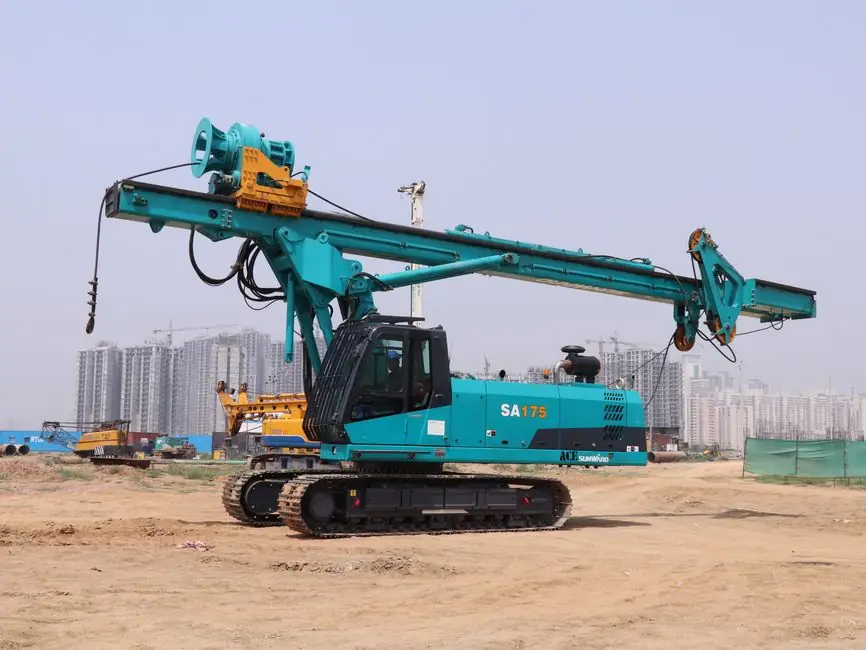
A defensible reaction calculation starts with a free-body diagram of the grab rig, guide rollers, suspended grab and guide wall, using the actual boom geometry, trolley position, rope angles and guide-roller spacing. A suspended grab is supported by ropes from a diaphragm wall rig or duty-cycle crane and operates hydraulically to excavate soil by opening and closing its jaws.
For an idealized trolley with horizontal reaction H at guide height h and vertical rope reaction V, the guide-wall horizontal force is H and the overturning moment is H times the distance from H to the guide-wall base. The soil reaction and machine weight then complete vertical equilibrium. Actual rope inclination changes the force components, so the simplified vertical and horizontal rope model should not be used where geometry produces a significant inclination angle.
Design Checks and Failure Modes
A guide wall can be constructed in-situ as a lightly reinforced concrete element to maintain horizontal alignment.
Diaphragm walls are normally reinforced concrete retaining elements with high flexural stiffness and relatively low deformation [S2]. However, wall-panel stiffness does not compensate for inadequate guide-wall support, because the guide wall acts before and during excavation while the panel system is incomplete. Circular diaphragm-wall analysis also identifies radial displacement, circumferential stress and vertical bending moment as separate wall responses, none of which should be substituted for the local guide-wall force check [S4].
Who Needs This Check

A grab may be suspended by ropes from a diaphragm wall rig or duty-cycle crane and operates hydraulically to excavate soil by opening and closing its jaws.
It is not a substitute for the permanent diaphragm-wall design. Permanent wall design depends on embedment, earth support, anchors, struts and the selected static system; supported and unsupported arrangements can be represented by beam-on-elastic-foundation methods [S2]. Circular walls also require treatment of circumferential arch action, a behavior not captured by a simple guide-wall beam model [S4].
The method is also unsuitable for estimating slurry pressure, reinforcement-cage insertion forces or concrete placing forces. Slurry stabilizes the open trench during excavation, while the guide wall controls geometry at its head [S1][S2].
Sourcing and Specification Discipline
Execution of diaphragm walls is described by DIN EN 1538, including the use of cutters or rope grabs with a guide wall to control trench line and level [S2]. The guide-wall reaction check must still use the selected rig geometry, roller details, concrete strength, reinforcement, foundation condition and site-specific construction sequence.
No single published source establishes a universal allowable mast reaction for a guide wall. The defensible deliverable is a coordinated temporary-works design showing calculated force, moment, bearing, shear, deflection and stability checks, supported by roller and connection details and the rig manufacturer’s load limits.
Track two signals before excavation: instrumented guide-wall and mast movement under representative digging cycles, and a signed temporary-works check that reconciles the calculated mast reaction with the guide roller, connection and foundation capacities.