The assessment covers rope-suspended and hydraulic grabs working in slurry-supported panels, with special attention to crane reactions, tracked undercarriage loading, verticality, and ground deformation in soft deposits [S1][S2][S4].
Separate Grab Capacity from Platform Capacity
These are equipment and operating ranges, not allowable platform loads.
A diaphragm wall grab can impose large vertical, horizontal, and dynamic loads as it penetrates slurry, closes on soil, lifts spoil, and stops suddenly. The crane and support system must therefore be checked for the actual boom geometry, suspended grab weight, soil resistance, trench-edge position, and operating cycle. A platform adequate for the stationary crane does not automatically qualify for repeated grab cycles [S1][S4].
Build the Soft-Ground Check Around the Real Load Path
A soft working platform should be assessed from the ground upward: crane outrigger or crawler loads, foundation mats or tracks, bearing or punching shear in the soil, and settlement that could alter crane stability. Track load distribution must be modeled from the machine geometry, including elevated working positions and any outrigger reactions; nominal machine mass alone is insufficient [S1][S4].
Three measurable controls should be required before excavation. First, the designer should verify allowable ground bearing pressure against the maximum crane and grab reaction. Second, the platform should limit differential settlement through load-spreading mats, compacted granular fill, timber or engineered platforms, and an effective drainage strategy. Third, the contractor should set limits for slurry level, spoil volume, crane radius, and the number of consecutive cycles at one panel.
Where the platform cannot demonstrate adequate bearing capacity, the practical options are ground improvement, replacement of the working surface, a reduced crane radius, or a lower-capacity excavation sequence. If hard or very hard ground requires a deeper trench, a rotary drilling rig or cutter-based method may be more appropriate than forcing a grab through an unsuitable load case [S2].
Compare the Principal Excavation Options
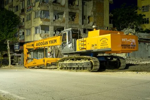
The method comparison should consider four decision criteria: ground suitability, trench depth, spoil removal, and verticality control. A cutter is favored in hard or very hard soil and at large trench depths, while a grab is suited to excavation in soils and very weak rock that can be loosened and removed mechanically [S2][S4].
For a soft platform, the correct choice is not always the machine with the greater nominal reach. It is the system that can excavate the required panel geometry while keeping crane loads, support-fluid demand, verticality, and ground movement inside defined limits.
Use Verticality and Monitoring as Early Warning Controls
Verticality should be measured as a trend from the guide wall downward rather than checked only at final depth. A changing trend can indicate grab reaction, guide-wall movement, platform settlement, or operator control issues before the panel reaches the base [S4]. The related procedure for setting diaphragm wall grab verticality by depth provides a method-specific reference for that control sequence.
Platform monitoring should include track or outrigger settlement, crane inclination, hydraulic pressure, grab opening and closing behavior, trench position, slurry level, and panel plumbness. Alarm thresholds must be tied to the geotechnical design and equipment limits, not selected from generic operating assumptions.
Manage Slurry, Overbreak, and Spoil as Separate Risks
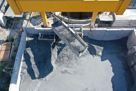
Support slurry prevents groundwater from penetrating the open trench and limits the breakdown of the existing soil [S2]. A soft platform still requires margins for these stages because leakage, surface erosion, and local pumping can reduce effective support and destabilize the trench edge [S2][S5].
The thickness of diaphragm walls varies between 0.6 and 1.1 m, and the panels are 2.5–6 m wide [S5]. Panel geometry and the guide wall must support tool positioning, safe access, near-surface stability, and reinforcement-cage placement [S4]. The guide wall therefore functions as a structural alignment and surface-control element, not merely a painted line.
The grab should not be treated as the only control on spoil volume. Closure at depth, slurry density, excavation sequence, panel length, and cutter or grab capacity all affect the load transferred into the trench [S1][S2]. Overfilled grabs can increase crane reaction, while poor slurry control can increase trench instability and ground loss around the guide wall [S4][S5].
Fit the Rig for Access, Support, and Service Life
Diaphragm wall construction uses a trench cutter or diaphragm wall grab to form adjacent rectangular panels that form a continuous retaining or cut-off wall. Once excavation is complete, joint elements and the reinforcement cage are inserted, and the trench is concreted [S1][S2]. Equipment access must account for the full sequence, not only grab deployment.
A rope-suspended hydraulic grab is positioned at the excavation panel by the diaphragm wall rig or crane, and trench excavation begins under slurry support [S1]. The crane must therefore provide stable reactions while the grab is inserted, closed, lifted, and emptied. Rope-suspended operation exposes the crane to changing suspended loads, while hydraulic closing mechanisms permit heavier and more compact grabs with less impact on the crane and more consistent productivity in some materials [S4].
Maintenance planning should include cylinder and hose condition, grab pivots and locking elements, slurry seals, hydraulic-fluid cleanliness, and undercarriage wear. A 210 bar nominal working pressure does not remove the need to verify relief settings, hose ratings, bypass behavior, and the pressure demanded by the complete actuator circuit [S3].
Set Acceptance Criteria Before the First Panel

Before excavation, the work package should define maximum crane radius, minimum platform bearing capacity, settlement limits, verticality tolerance, slurry limits, spoil-volume limits, and stop-work triggers. The platform acceptance calculation should be based on the worst credible load combination, while monitoring points should be installed before the guide wall is heavily loaded [S1][S4].
For soft ground with high groundwater pressure, diaphragm walling remains a practical retaining solution, but weak rock, limited site access, and construction constraints can favor cutter technology over grab excavation [S4]. Where the dynamic compactor is used for ground improvement, its operating specification and ground treatment objectives must remain separate from the grab’s 400–800 tonne per-cycle capacity [S3].
The next trackable signal is the first instrumented crane cycle: compare platform settlement, crane inclination, hydraulic pressure, grab cycle time, slurry level, and verticality against the approved operating envelope. A stable opening cycle does not prove long-term platform capacity, so acceptance should continue across repeated excavation, desanding, and panel-change movements.