Correct soft starter installation requires a qualified electrician, verified voltage and motor-current ratings, safe isolation, manufacturer-specific wiring, and controlled commissioning.
ABB PSS18/30-500 to PSS175/300-500 soft starters cover low-voltage motor starting applications, while Eltwin SSxB units use 115/230 V single-phase HVAC wiring and require a separate contactor [S1][S2].
Verify the soft starter and motor before mounting
Confirm that the soft starter voltage rating matches the motor circuit, and that its rated current is at least equal to the motor full-load current. ABB specifically requires checking system voltage, rated motor data, and connection type before installation [S1].
Choose the wiring arrangement to match the application: inline for a basic reduced-current start, bypass contactor where the motor must run at full voltage for extended periods, or inside-the-delta for a six-wire motor arrangement [S3]. Check enclosure space, mounting provisions, cooling clearance, and the required environmental rating before placing the unit in the panel [S3].
For an Eltwin SSxB 115/230 V unit, the field wiring uses 8–12 AWG stranded copper for the Run Winding and Active terminals, and 12–16 AWG stranded copper for Run Capacitor, Start Winding, and Compressor or Motor Common terminals. The supplied conductors must be rated for at least 167°F, or 75°C [S2].
Isolate power and prepare the mounting location
Disable the equipment at its breaker or disconnect, apply lockout and tagout, and verify that every phase is at zero voltage before touching terminals.
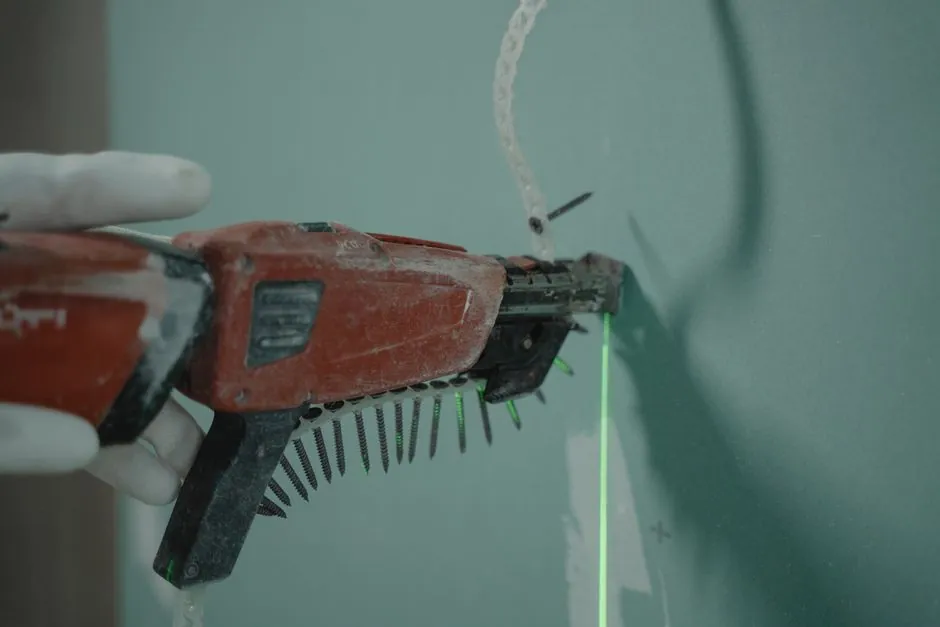
Mount the soft starter on its specified bracket, DIN rail, or panel surface without obstructing airflow. ABB PSS18/30-500 to PSS175/300-500 models include model-specific drilling plans and minimum wall or front clearances, so those dimensions must be taken from the relevant product section rather than copied from another model [S1].
Its listed enclosure is 10 in. × 8 in. × 6 in., and all field conductors must use conductors rated for 75°C or higher [S2].
Wire the power circuit without reversing motor phases
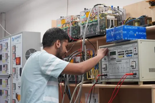
Connect the supply to the line-side terminals and the motor to the load-side terminals identified in the soft starter manual. Incorrect phase sequence can damage the motor, while an incorrect line or delta connection can prevent the expected acceleration [S1][S3]. Do not infer terminal function from physical position when labels or the wiring diagram are missing.
Terminate conductors with the specified tools and tighten terminals to the stated torque. Eltwin specifies 11.5 lb-in for its large terminals and 4.5 lb-in for its small terminals, and warns that loose terminals can cause heating and subsequent soft starter damage [S2].
Connect protective earth and install the branch-circuit disconnect or breaker under the applicable motor-circuit rules. The disconnect must be sized and arranged for the motor installation, while the soft starter must be checked against the motor full-load current rather than protected solely on the starter’s bypass rating [S3].
Connect controls and select the correct start method
Wire the separate control circuit for start, stop, reset, reference, and any voltage or current measurement required by the product. A missing control connection can trigger unnecessary faults, and incorrect connections can disable fault protection or expose the motor to abnormal operation [S3].
Set the start ramp, stop ramp, initial voltage, and current limit using the application table for the motor and load [S1]. The line/delta switch must agree with the actual motor connection, since a mismatch changes the effective starting arrangement [S1].
Its start capacitor is integrated, but the SSxB acts only as a soft starter and still requires a contactor [S2]. Do not interchange the Run and Start winding connections [S2].
Commission in stages and verify motor direction
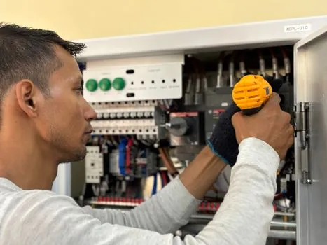
Inspect every termination against the manufacturer’s circuit diagram, confirm that covers and barriers are restored, and perform a no-load test before connecting the full mechanical load [S3]. Confirm that the motor accelerates in the intended direction, that the soft starter reaches its running state, and that no bypass contactor remains incorrectly energized during controlled starting.
Next, test at the intended load and check starting current, acceleration time, motor rotation, and fault status. A soft starter without a bypass contactor can overheat SCRs if it is used to carry continuous running current beyond its intended design [S3]. The ABB troubleshooting procedure should be used if the unit does not start, trips, or behaves differently from the configured ramp [S1].
Record the configured U INI, I LIM, start ramp, stop ramp, and line/delta position, then attach that record to the installation file. This creates an objective baseline for later maintenance and makes a changed setting distinguishable from an internal device fault [S1].
Diagnose faults by symptom rather than repeated resets
If the motor does not start, first verify incoming power, the external contactor, control-circuit commands, and terminal security. Phase reversal, an open control connection, or a mismatched line/delta setting can create the same apparent start failure, so replace random parameter changes with point-by-point circuit checks [S1][S3].
If the unit trips on overcurrent, verify the motor FLA, I LIM setting, load condition, and power quality before increasing the limit. On an Eltwin SSxB, a low-voltage lockout follows 3 failed starts, while the documented fault indications include rapid flash at 10 flashes per second, triple flash at 3 flashes per 3 seconds, slow flash at 1 flash per 3 seconds, and steady flash at 1 flash per second [S2].
If abnormal heating develops, de-energize the equipment and check for loose terminals, blocked ventilation, excessive starting frequency, or a bypass arrangement that is not operating as designed. The Eltwin instruction specifies allowing 2 minutes for the run capacitor to discharge before disconnection, and ABB defines dedicated troubleshooting, thyristor-module replacement, and printed-circuit-board replacement procedures for its PSS range [S1][S2].
Select a soft starter or VFD by duty requirements
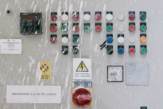
A soft starter reduces the initial voltage and current applied to a motor, while a VFD controls speed and torque throughout the operating range. For a fixed-speed motor with only high starting current as the problem, a correctly rated soft starter is generally the simpler choice. Where process flow must vary continuously, the additional control capability of a medium-voltage VFD becomes relevant [S3].
The decision can be reduced to four criteria. First, compare required speed control: neither a standard inline soft starter nor a VFD is needed for a fixed-speed process, while a VFD is required for commanded speed variation. Second, compare starting performance: the soft starter uses U INI, I LIM, and ramp settings, while a VFD provides closed-loop frequency and torque control. Third, compare continuous running architecture: a soft starter may require a bypass contactor to avoid SCR heating during continuous operation, while a VFD uses different semiconductor switching arrangements [S1][S3]. Fourth, compare commissioning scope: the soft starter path requires power and control wiring, a configured ramp, and direction verification, while the VFD path also requires motor and control-parameter validation [S3].
Apply product-specific limits and standards
Do not apply one manufacturer’s clearances, wire sizes, or torque values to another model. The ABB manual covers PSS18/30-500 to PSS175/300-500, PSS50/85-500 to PSS85/147-500, and corresponding 690 V variants, with mounting and connection details organized by product family [S1]. The Eltwin guide covers the SSxB 115/230 V single-phase series and specifies a contactor, 75°C conductors, terminal torques, ferrule geometry, and an enclosure size of 10 in. × 8 in. × 6 in. [S2].
UL 508 is cited in the Eltwin guide for terminal tightening and loose-connection risk, while the installation work must also comply with applicable local electrical and motor-circuit requirements [S2][S3]. For industrial motor applications, the broader equipment architecture and commissioning choices can be compared with Soft Starter vs VFD Selection for Centrifugal Pump Duty.
Complete the installation file with the verified motor FLA, supply voltage, wiring method, terminal-torque check, fault settings, and no-load and loaded test results. Recheck these records during the first maintenance interval, with particular attention to tightened conductors, cooling clearance, bypass operation, and any change in starting current.