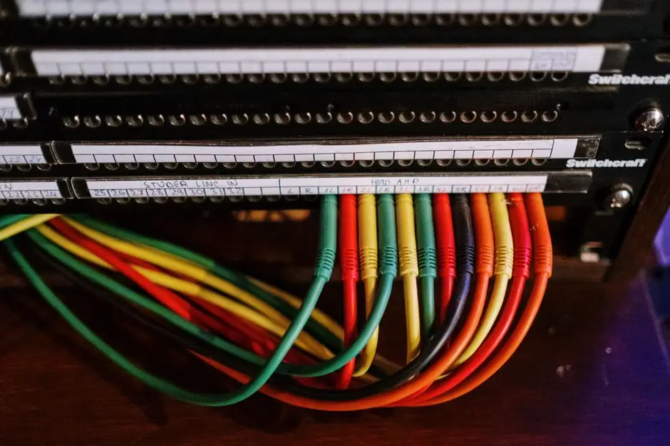
A correctly installed terminal block uses manufacturer-specified conductor sizes and tightening torque, with DIN rail end stops and no exposed conductor beyond the intended ferrule or termination point [S1][S3].
This guide covers panel, distribution-board, and junction-box installation, including screw, push-in, barrier, PCB, and grounding configurations for industrial control, machinery, and building electrical systems [S1][S3][S6].
Select the terminal block from circuit requirements
Current, voltage, conductor size, pole count, and module pitch determine whether a terminal block is electrically suitable [S3]. When selecting a terminal block, consider the expected current, voltage, conductor size, pole count, and module pitch, and confirm that the conductor, insulation, mounting method, and surrounding components are suitable for the load [S3].
Voltage selection must cover the application voltage and any identified surge conditions, while pitch must allow the intended number of poles without violating spacing, access, or enclosure limits [S3]. Do not transfer a rating from a related module: a feed-through, protective-earth, fuse, or multi-level block may share a housing style but not the same electrical function or approvals [S3].
For an overview of the physical connection format and common block families, see terminal blocks. Industrial assemblies may also contain circuit breakers, but their individual installation procedures must not be inferred from terminal-block instructions.
Prepare the panel and preserve circuit identification
DIN rail installation requires a firmly mounted rail, correctly positioned blocks, and end stops that prevent sliding or impact from moving the row [S1]. Before wiring, isolate the circuit, verify absence of voltage, and record the circuit schedule so that each conductor can be traced to its intended terminal [S1].
Strip insulation only to the length required by the terminal manufacturer, remove damaged strands, and fit ferrules to stranded conductors where required [S1]. The prepared conductor should retain the insulation rating needed for the installed voltage and must not leave copper exposed beyond the permitted termination zone [S1][S7].
Use green/yellow identification for protective-earth conductors and mark every wire and terminal consistently with the panel drawings [S1]. Cable strain relief and conductors secured near the terminal prevent mechanical loads from transferring into the clamping point [S1].
Compare screw and push-in connection methods

Screw terminals require a calibrated driver set to the manufacturer’s specified torque, while push-in terminals require a conductor prepared to the published insertion length and inserted until the spring clamp is fully actuated [S1]. Neither method permits an arbitrary substitute, such as twisting a conductor by hand or clamping it in a terminal designed for a ferrule.
The comparison reflects the installation characteristics described in [S1]. Final selection still depends on the manufacturer’s ratings for each exact module, including conductor cross section, current, voltage, and connection count; the general preference for one technology must not override those limits [S1][S3].
Install screw, barrier, and special-purpose blocks
For a screw-type barrier installation, place the terminal block inside the terminal box, fit the two hold-down screws, and remove the specified brass nut, washers, and links before placing the connection hardware [S4]. Where a link is required, seat it against the ring terminal rather than separating the link from the terminal with a washer or nut, because the extra joint can create high resistance and motor failure [S4].
Reassemble the hardware in the specified order, tighten the bottom nuts first, then install the ring terminal, link, washer, and upper brass nut, and confirm that all nuts are secure [S4]. This sequence applies to the cited motor-terminal installation arrangement, not automatically to compact DIN rail modules whose manufacturer's instructions may specify a different clamping mechanism [S4].
Protective-earth blocks may connect the conductor to the DIN rail or panel rather than joining two insulated wires [S3]. Use the block designated for that function, follow its conductor and bonding instructions, and do not substitute a neutral or feed-through block merely because its housing dimensions match [S3].
Prevent loose connections, overheating, and exposed copper
Loose connections, overheating, and exposed conductor are common installation failures addressed by control of strip length, conductor preparation, clamping, and torque [S1]. One wire per connection is a useful default when the terminal specification permits only one conductor, but the exact module instructions control where multiple conductors, stacking, or jumpers are allowed [S1].
Symptom-to-action sequence: a conductor that moves under gentle inspection indicates inadequate insertion or clamp force, so re-terminate it rather than adding more torque blindly; visible copper beyond the housing indicates incorrect stripping, so shorten and re-prepare it; a browned or heat-damaged terminal indicates an overloaded or high-resistance connection, so de-energize the circuit, identify the cause, and replace the heat-damaged component [S1].
Do not repair a loose or overheated terminal merely by adding strands, extra washers, or another improvised conductive interface [S4]. Replace damaged terminals or conductors when their integrity is uncertain, and escalate recurring faults to the circuit designer because they can indicate incorrect conductor sizing, insufficient ventilation, or an undersized connection [S1][S3].
Test, mark, and document the finished installation
Verification should cover at least 4 conditions: every terminal matches the wiring schedule, every screw is tightened to the specified torque, every push-in conductor is fully inserted, and no exposed copper or loose strand remains outside the intended termination zone [S1][S7]. A visual inspection does not replace a torque check because a terminal can appear seated while its clamp force is inadequate [S1].
Before energization, perform continuity or continuity-and-resistance checks as required by the approved circuit procedure, verify separation between conductive parts, and confirm protective-earth continuity through the designated earth terminal [S1]. The commissioning sequence for adjacent protection equipment, such as the circuit breaker installation guide for safe commissioning, must follow the approved panel test plan rather than substitute for terminal-level verification.
Industrial panel terminal blocks are identified in the supplied material with IEC 60947-7-1 and UL 1059, while installation practices must also comply with the jurisdiction-specific electrical code and the selected product’s certification [S1]. Record the product type, conductor range, torque value, test result, panel revision, and installer identification so future maintenance does not depend on memory.
Before releasing the panel, verify one marked circuit end to end, confirm all specified torques are documented, inspect the DIN row for secure end stops, and compare every terminal label against the approved circuit schedule [S1][S3].