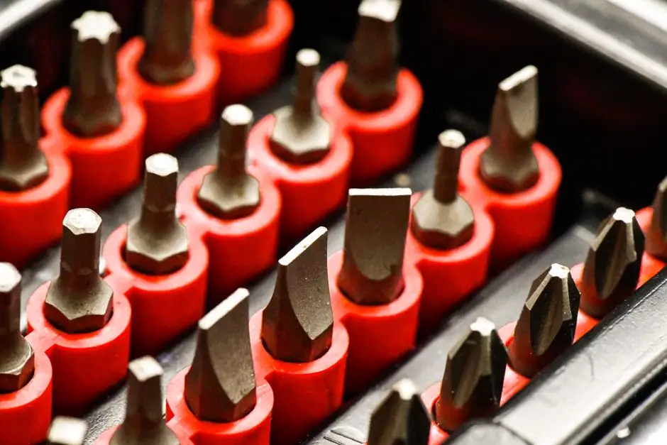
A standardized mold base that accepts interchangeable cavity and core inserts is a well-established architecture: the mold base remains bolted in the press while the operator swaps only the functional inserts, a configuration the technical literature calls a "rapid interchangeable-insert" or "cassette" mold [S2][S5]. The opposite reference architecture is a dedicated mold base, in which cavity, core, cooling, and ejection are built into one tool sized for a specific part and cavitation count [S4].
Both architectures are explicitly covered by automotive OEM tooling standards, which call out a "mold base for inserted cavity sets" alongside porous cavity and core inserts for venting as required elements of an interchangeable insert system [S3]. For a process engineer, the practical question is not which is "better", but which matches the production volume, part envelope, and life expectancy of the program [S4].
How Interchangeable-Insert Architecture Actually Works
Removable and replaceable core and cavity inserts were already described in 1973-era injection-mold patent literature, where a "mold base of generally standard construction" receives inserts "into the cavities in which they are disposed" [S5]. In a modern rapid interchangeable-insert (RIC) system, the exchange is deliberately limited to the functional cavity and core inserts while the mold base remains installed on the press, which is the defining feature separating this class from a full tool change [S2].
Shop-floor practice documented on machining forums shows the inserts seated into pockets machined in the standardized base, with a recommended interference of about 0.001 in (0.025 mm), i.e. the insert is left "proud" of the pocket to keep parting-line contact clean and repeatable [S6]. For a deeper reference on the base side of that stack-up, the mold base encyclopedia entry covers the standard A-plate / B-plate / support-plate construction those pockets are machined into. Related reference material on the broader casting tooling family is also useful when the same machine is asked to run die-cast or sand-cast changeovers alongside injection.
Selection Criteria: When to Use Standardized Base + Inserts
The decision is driven by four numbers: annual volume, part envelope, cycle life target, and program life expectancy. Woodland Plastics' engineering comparison is explicit: a dedicated mold base offers higher total mold life and is sized only by the press footprint, while MUD (Master Unit Die) inserts are limited to the MUD frame footprint and "will generally be limited to running one or two cavities at a time in a MUD frame" [S4]. That single statement sets the architectural boundary for most programs.
Use standardized base + interchangeable inserts when the part footprint fits the standard frame, the annual volume is modest (the source describes this as "smaller parts with lower annual volumes" [S4]), the program life is short, or you need prototyping flexibility without committing to a full production tool. Use a dedicated mold base when the part is large or intricate and the standard frame cannot accommodate the geometry, when the program requires multi-cavity throughput that the standardized frame cannot physically hold, or when the target cycle life exceeds the practical insert life before refurbishment [S4]. A practical reference for sizing that dedicated base is the P20 vs 1045 steel mold base plate guide, which maps steel grade to expected tool life. For steel-hardness targets on the base side, the mold base steel hardness spec article gives the HRC window typical for long-life injection tooling.
Standards, Footprints, and Cross-Supplier Interchangeability

The standardized base only delivers its promised flexibility if suppliers honor common footprints, which is why OEM documents such as the Adient PS Injection Mold Tool Standards treat the "mold base for inserted cavity sets" as a named line item with porous cavity and core inserts for venting slotted and vented to a standard stock diameter [S3]. The DME A-series mold-base line is the de facto footprint reference for North American shops; cross-supplier interchangeability on that footprint is detailed in the DME mold base interchangeability reference.
Two practical points follow from those standards. First, cooling and ejector lines must be re-plumbed or re-pin-aligned each time inserts change, which is why the standardized base is typically built with repeatable quick-disconnect circuits and pre-machined ejector pin bores rather than custom-drilled passages [S3]. Second, the standard does not eliminate the need for a per-part DFM review, because parting-line shut-off, gate location, and slide action are still part-specific, even on an interchangeable insert; RapidDirect's overview of core vs. cavity in injection molding walks through that geometry dependency. The related mold base encyclopedia entry restates the standard plate stack-up that the inserts seat into.
Cost, Lead-Time, and Cycle-Time Trade-Offs
Cost reduction is the dominant driver for the interchangeable architecture. Rapid Axis quantifies the multi-cavity logic by noting that "if you can manage two cavities in one mold, you can essentially cut your tooling cost in half" because you get two cavities for roughly the price of one mold, and that a single tool can run parts "20 times faster" when scaled into double-digit cavity counts for small parts [S1]. That arithmetic inverts for the standardized base: the base is built once and amortized across many insert pairs, so each new insert-only changeover is a fraction of full-tool cost.
Lead-time is the second axis. A full dedicated mold base, especially for large parts, involves machining, heat treatment, and tryout of the entire assembly. The interchangeable path runs the same tryout once on the base, then ships only the inserts for each new part. The patent literature already framed this as the economic logic of the "cassette" mold concept: one standardized base, many removable and replaceable core and cavity inserts [S5]. The trade-off is reduced cavitation: a MUD frame is generally limited to one or two cavities, versus multi-cavity dedicated bases that can run the same part four-up or more in a single shot [S4][S1].
Failure Modes and Limitations
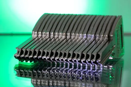
Interchangeable-insert systems have well-documented limits. Insert seating is the most common source of flash and dimensional drift, which is why shops specify a controlled interference around 0.001 in (0.025 mm) of the pocket and verify with a dial indicator at each changeover [S6]. Cooling-line mismatch between the base and the new insert is the second failure mode, because a different insert geometry typically changes the heat-extraction path; if the standardized base lacks dedicated circuit zoning, the cycle time will drift part-to-part.
Third, the standardized architecture has a ceiling on total cycles per insert, after which the cavity or core must be reworked or replaced; in the dedicated-base path, the entire tool is built to a higher life target and is not limited by a single insert's fatigue life [S4]. Fourth, large or highly intricate parts physically do not fit the standard frame, and forcing them into one will compromise slide access, ejector layout, and cooling, which is why the literature treats frame-fit as a hard gate rather than a soft preference [S4]. The casting mold encyclopedia entry covers the related constraint set for cast parts run on the same frame philosophy.
Use Cases and Decision Matrix
Three concrete use cases clarify the call. (1) Bridge production and prototyping at 5,000-50,000 parts per year for a small enclosure: standardized base + single or two-cavity inserts, accepting the 0.001 in seating tolerance and per-part cooling limits in exchange for a tool cost that is a small fraction of a dedicated build [S4][S6]. (2) Family mold for a sub-assembly where four different parts must run in the same press on a single material, with modest annual volume: standardized base + four insert sets, leveraging the fact that a family mold is acceptable when "the whole assembly uses the same material" [S1]. (3) High-volume automotive interior program running into the millions of cycles on a complex geometry: dedicated mold base, multi-cavity, hardened to the HRC window covered in the mold base steel hardness spec article.
The decision matrix reduces to four rows. Cavitation count: 1-2 cavities favors standardized base; 4+ favors dedicated. Annual volume: under roughly 50,000 parts favors standardized; over 500,000 favors dedicated, with the crossover roughly at 100,000-200,000 depending on part size. Part envelope: inside the standard frame footprint favors standardized; outside forces dedicated. Program life: under 3 years or uncertain forecasts favors standardized; 5+ year programs with stable geometry favor dedicated. These thresholds are not pinned in the source material, so treat them as engineering rule-of-thumb bracketing rather than certified limits.
The next signal worth tracking is the 2026-vintage peer-reviewed work on rapid interchangeable-insert (RIC) molds with in-press shut-off adjustment, which directly targets the seating-tolerance and cooling-drift failure modes above by allowing the insert to be re-aligned while the base stays in the press [S2]. Watch for published cycle-time deltas and any revision to the Adient PS Injection Mold Tool Standards that codifies the in-press adjustment into the standard footprint [S3].