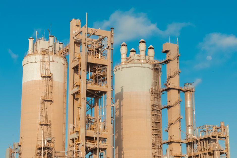
Saturated shell boilers typically discharge steam at a 95–98% dryness fraction, and the residual 2–5% moisture must be removed by pipeline separators before the steam reaches control valves, heat exchangers, and flowmeters [S2].
Specifying a separator in 2026 still resolves to three families — baffle/vane, cyclonic, and coalescence (mesh) — each with a different pressure-drop, entrainment-separation, and dirt-loading profile; the application, not the price list, sets the family [S2].
Why 'wet' steam is the problem a separator must solve
Steam leaving a shell boiler is inherently wet because boiler water is entrained with the steam; priming and carryover events push that moisture figure even higher, and distribution-pipe heat loss condenses additional water that re-enters the flow as a film and then as droplets shed from wave crests [S2].
That entrained water cuts heat-transfer efficiency — water films act as a thermal barrier across exchanger surfaces — and accelerates wear: high-velocity droplets erode valve seats (a failure mode called wiredrawing), raise corrosion rates, scale heating surfaces, and destabilise control valves and flowmeters until they fail outright or suffer waterhammer [S2].
Steam trapping downstream of drip legs removes the bulk condensate, but it cannot reach the micron-scale droplets held in suspension, which is why a separator stage is non-negotiable on any distribution line feeding process loads [S2].
The three separator families — how each one removes moisture
Baffle (vane) separators force the flow through a series of direction changes across internal plates; droplets with higher mass and inertia cannot follow the steam around the baffles and impinge on the plates, while the enlarged cross-section also drops fluid velocity, reducing droplet kinetic energy so most of them fall out of suspension into a bottom pocket drained through a steam trap [S2].
Cyclonic separators use internal fins to impart high-speed swirling motion, throwing the heavier water phase to the vessel wall; the coalesced film runs down to a trap mounted directly beneath the body, which makes the cyclonic family the default pick on higher-velocity lines where baffle pressure drop would be unacceptable [S2].
Coalescence (mesh/demister pad) separators present a fine wire-mesh obstruction across the steam path; droplets impact the wires, coalesce into larger droplets, and fall out of the gas stream — a geometry that gives very high entrainment separation at the cost of dirt loading and a finite blow-down cleaning interval [S2].
Selection criteria — flow regime, pressure drop, dirt, and layout
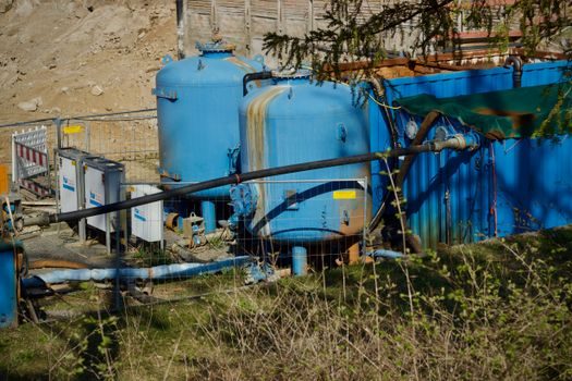
Selection starts with the operating flow regime rather than the line size: baffle separators are inexpensive and tolerate dirty steam but carry the highest pressure drop per unit moisture removal, cyclonic units give moderate pressure drop at high separation efficiency and are forgiving on flow turn-down, and mesh/coalescence types deliver the lowest residual moisture at the cost of the highest sensitivity to fouling [S2].
Three figures must be on the datasheet before the family is locked in: the design mass flow (kg/h), the allowable pressure drop across the separator (typically expressed in bar or as a percentage of upstream line pressure), and the target outlet dryness — process loads such as pharma clean steam and turbine-driven linear guide lubrication-air dryers often demand outlet dryness above 99%, while general plant heating steam can run on the 98% figure [S2].
Lay-out then constrains the choice: baffle and cyclonic separators need a straight inlet run of several pipe diameters and a vertical-down condensate pocket with a dedicated steam trap, whereas horizontal-pipe coalescence units are often chosen where the line cannot be lifted into a vertical vessel.
Comparison — baffle vs cyclonic vs coalescence on four decision criteria
On pressure drop at equal entrainment removal, baffle separators sit highest, cyclonic units are mid-range, and mesh/pad coalescence units are typically the lowest — but the mesh unit's advantage reverses the moment the steam carries iron oxide, scale, or process solids, because the pad plugs and the differential pressure climbs until the unit is bypassed [S2].
On dirt tolerance, baffle is the most forgiving, cyclonic is intermediate, and coalescence is the most sensitive — operators running mesh separators on dirty steam budget for periodic blow-down or pad replacement, and a cyclone separator geometry is usually specified in its place when solids loading is non-trivial.
On turn-down (low-flow behaviour), cyclonic separators maintain swirl down to roughly 30–50% of design flow before separation efficiency collapses, baffle separators are more sensitive to low flow because droplet inertia depends on velocity squared, and mesh units degrade more gradually because the pad is still collecting droplets at low velocity — albeit at lower absolute efficiency [S2].
On installed footprint, cyclonic vessels are the most compact per kg/h of separated water, baffle units are mid-pack, and mesh units are usually the longest because the pad depth sets the vessel length, which is a real constraint on retrofit work in existing pipe racks.
Where separators sit in the steam system — sizing and integration
Separator sizing is a velocity problem: the internal cross-section must drop the steam velocity below a value at which suspended droplets can no longer stay aloft, with typical process design targeting 25–35 m/s inlet for the separator body in saturated service and lower velocities in superheated lines [S2].
In a real distribution header, the separator is installed just upstream of every branch that feeds a process load with tight dryness requirements — heat exchangers, control-valve stations, and turbine drives — and it is paired with a steam trap sized for the expected condensate load, because the bottom pocket only collects water; it does not discharge it [S2].
On pulp-and-paper lines, mechanical-pulping refiners use a different category entirely — the Valmet Steam Separator PF is a mechanical separator that lifts fibres out of the steam flow before the steam is fed into the second or third stage refiner, which is process-equipment separation rather than moisture removal from a steam distribution line [S3].
Limitations, failure modes, and what separators do NOT fix
No separator can compensate for a saturated boiler running with excessive priming, and a separator installed downstream of a poorly managed boiler will simply collect water faster than its trap can discharge it, leading to waterlogging and waterhammer risk on the line [S2].
Mesh-pad coalescence units fail by fouling — iron oxide, pipe-scale, and lubricant carryover blind the pad, pressure drop rises, and the separator is often removed entirely by maintenance crews who do not recognise the symptom, after which wet-steam damage reappears on downstream valves [S2].
Baffle separators fail by erosion of the baffle plates over years of wet-steam service, and cyclonic separators fail when the internal fins are damaged or when the drain leg is plugged, which re-introduces the very water the separator was installed to remove [S2].
For process and reliability reference on adjacent equipment classes, see the spec coverage of steam separators and the application boundaries of cyclone separators used in two-phase flow service.
Standards, sourcing, and what to verify on the data sheet
Steam separator bodies are typically supplied to ASME B16.5 / B16.34 valve-and-fitting geometry and PED 2014/68/EU for European pressure equipment, with material selection (carbon steel, stainless 304/316, or duplex) driven by the cleanliness and corrosion profile of the condensate rather than the steam itself [S2].
Verification points on a 2026 vendor data sheet should include: design pressure and temperature, saturated steam capacity in kg/h, allowable pressure drop at that capacity, separator type and internal geometry (baffle / cyclonic / mesh), recommended trap size and trap model, and a documented blow-down or pad-cleaning interval for coalescence units [S2].
Cross-spec the trap to the condensate load — a separator that drains a saturated 10 bar line at 5 t/h of steam can produce condensate in the tens of kg/h range under cold-start conditions, and an undersized steam trap will waterlog the pocket even when the separator internals are correctly selected [S2].
For installations feeding precision motion hardware, a separator mounted upstream of a turbine-driven linear guide actuator package is a hard requirement, because wet steam at control-valve orifices is the dominant failure mechanism for that equipment class.
Trackable signals for 2026: vendors publishing verified dryness-fraction test data (inlet vs outlet, with a recognised test method) rather than marketing-only efficiency curves, and EPCs starting to specify mesh-pad replacement intervals in operating manuals rather than leaving them to maintenance judgement.
For related coverage, see Green Hydrogen Upstream and Downstream: 2026 Project Pipeline and Spec Map.