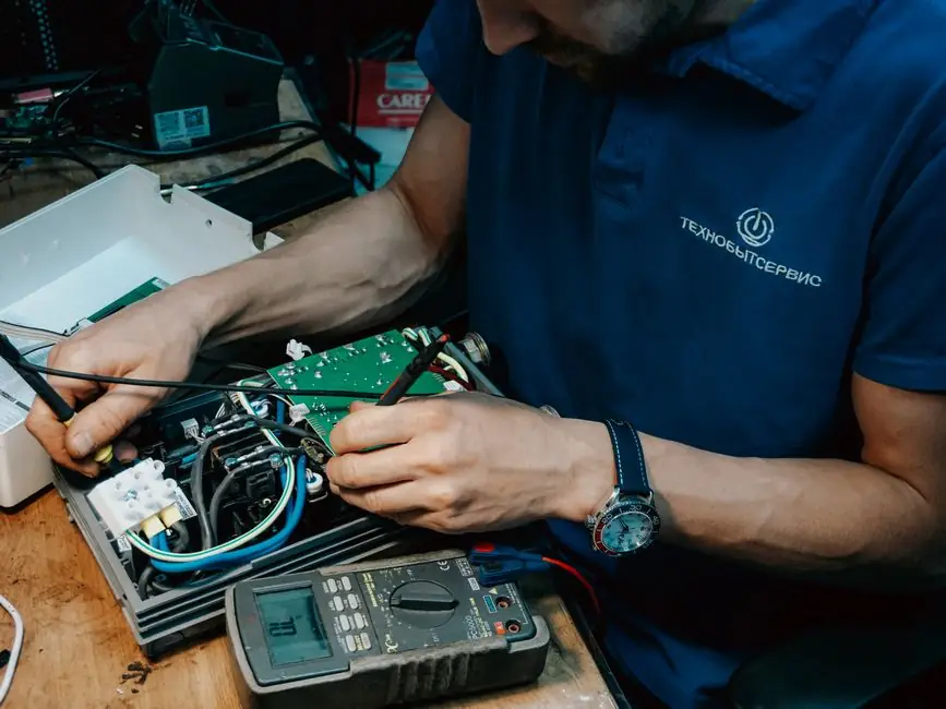
A correctly installed stepper drive delivers commanded pulses as controlled winding current [S2][S4].
This guide covers bipolar and unipolar motors, screw-terminal wiring, current selection, cooling, fault checks, and startup validation for industrial stepper drives [S1][S3][S5].
Match the Drive to the Motor Wiring and Current
Bipolar motors use two windings and require each winding lead to be driven in either direction, while unipolar motors use tapped phase windings and typically need multiple supply connections [S4]. Before wiring, identify the motor schematic, wire colors, coil arrangement, rated voltage, and current from the motor documentation rather than relying on lead color alone [S1][S5].
For a dual-phase motor, confirm whether an 8-lead winding is connected in series or parallel. The Kollmorgen 5220 manual documents separate procedures for 4-lead, series-connected 8-lead, and parallel-connected 8-lead motors, including phase polarity and terminal mapping [S5]. Incorrect phasing can prevent startup, produce violent reversal, or cause the drive to report a fault.
The MachMotion guide states that its micro-stepping drive can control different types of stepper motors and uses screw terminals for motor connections [S1]. Do not exceed the motor, drive, connector, or wiring ratings.
Choose L/R, Bilevel, or PWM Drive Architecture
L/R drives use series resistance to limit winding current, bilevel drives control current by switching between voltage levels, and PWM drives use pulse-width modulation to regulate current through the windings [S3]. The architecture affects current rise time, high-speed torque, heat, and motion quality.
L/R, Bilevel, and PWM are three basic stepper driver and controller categories [S3]. They provide rated running torque mainly at low to moderate speeds because current cannot be raised dynamically as speed increases [S3]. A stepper driver and controller provide the rated motor phase current by chopping the input supply voltage, and the inductive time constant, τ = L/R, affects the rate at which current flows [S3].
A bipolar stepper motor has four wires and two coils, and current is driven through the coils to make the motor rotate [S4]. More microsteps do not guarantee more accuracy because motor, drive, mechanics, and load compliance determine the achieved positioning error.
Wire Pulse, Direction, Enable, and Power

Disconnect power before changing motor or control wiring. The documented MachMotion control connector uses PUL+, PUL-, DIR+, DIR-, EN+, and EN-, with pulse and direction inputs controlling commanded movement and enable determining whether the drive can energize the motor [S1].
Connect motor phases to the drive's power or motor connector, then connect the controller output to the control input. The Kollmorgen 5220 hardware reference identifies J3 as the motor connection [S5]. Connector assignments are equipment-specific, so use the selected drive's manual rather than transferring a pinout from another model.
Use shielded control wiring for pulse, direction, and enable signals, keep it separated from high-current motor and supply wiring, and terminate shielding according to the drive and controller instructions. For an open-collector pulse source, confirm whether the drive accepts 5 V, 12 V, 24 V, or another interface level. A 24 V output applied to a 5 V input is an electrical fault, not a configuration preference.
Configure Step Size, Current, and Direction
Set the drive's configuration switches to the motor phase count, rated current, and desired step mode before energizing the motor [S1].
Commanded direction depends on pulse order, direction-polarity logic, and motor phase wiring. Establish a known jog direction with the motor mechanically unloaded, then verify that positive command produces the intended positive axis. If direction reverses when the wiring is changed, correct the phase mapping or polarity setting rather than compensating in the machine program.
Full-step operation provides the basic angular increment, half-step energizes both coils between full-step positions, and microstepping modulates current to create intermediate positions [S2][S4]. Microstepping commonly reduces acoustic noise and makes motion smoother [S4], but it can increase commanded resolution without improving the machine's absolute positioning accuracy.
Mount the Drive and Protect the Cooling Path

Mount the drive away from conductive debris and maintain the airflow specified for the model.
Do not install the drive in a sealed enclosure without a calculated heat path. A clean enclosure with unfiltered air can also be unsuitable because conductive dust can bridge terminals or contaminate cooling passages. For panel work, follow the drive manufacturer's grounding and conductor-size instructions, then verify terminal torque against the specified value.
The MachMotion unit is specified for 120 VAC supply, with an absolute maximum of 130 VAC, and lists an 80 °C temperature specification [S1]. Those limits apply to that model and must not be transferred to another drive. If the required supply differs, replace the drive with a model whose input range, phase count, current, and environmental ratings match the machine.
Resolve No-Motion and Fault Symptoms Before Startup
If the motor does not move, first verify that the drive's Signal LED flashes when step pulses are commanded. MachMotion identifies this LED as active while step and direction pulses enter the control connector [S1]. If the LED remains off, check the controller output, enable wiring, supply voltage, and the setting of the control connector rather than changing motor leads.
If the Fault LED illuminates, record the fault condition and remove its cause before restarting. The MachMotion guide states that its Fault LED is cleared by repowering the drive after the fault has been corrected [S1]. Repeated power-cycling without diagnosis can repeatedly stress the drive and leaves the root cause in place.
For a bipolar H-bridge implementation, never energize the two switches on the same supply leg simultaneously. That state creates a low-resistance path from supply to ground and can damage the switching devices [S4]. If the shaft buzzes but does not rotate, stop the command, verify coil phasing, reduce commanded speed, and check whether the load is mechanically jammed.
Validate Motion, Torque, and Positioning
Perform the installation test with the drive, motor, and controller connected, but initially without a production load. The 5220 procedure requires a motor plus a computer or terminal to test the installation after power-up [S5]. Confirm power, enable state, pulse activity, intended direction, and repeatable movement before attaching the mechanism.
Then run through the intended speed and travel range at low acceleration. Watch for lost steps, collision, excessive vibration, rising drive temperature, and audible resonance. The 5220 manual includes a dedicated section on low-speed resonance, which can appear as severe vibration or noise rather than an obvious electrical failure [S5].
Measure positioning repeatability at multiple points rather than relying on commanded step counts. A 200-step motor with 16 microsteps per step commands 3,200 positions per revolution, but useful repeatability can still be limited by backlash, shaft runout, resonance, and structural deflection. Compare the measured result with the application's tolerance, then reduce speed or acceleration where the drive cannot maintain stable motion.
Apply the Acceptance Sequence Before Release
A complete installation should pass a defined sequence: verify the motor schematic and phase mapping, confirm series-current rating, inspect every motor and control terminal, set current and step mode, check cooling spacing, verify signal activity, jog direction unloaded, test travel and repeatability, and then repeat the test under production load [S1][S3][S5].
Use the equipment-specific manual as the controlling document. The Kollmorgen reference is Revision D, dated September 1997, while the Kollmorgen 5220 installation and hardware reference covers power-up testing, maintenance, troubleshooting, 4-lead and 8-lead connections, current control, step size, idle current, low-speed resonance, and phasing [S5].
The release record should include the drive model and serial number, motor model, wiring configuration, current setting, microstep setting, supply voltage, measured repeatability, and thermal observation. That baseline makes the next fault diagnosable instead of turning every malfunction into a motor replacement.