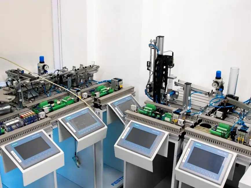
A servo drive installation should be accepted only after the mechanical load, motor ratings, feedback device, protective earth, and control wiring have been verified.
The guide covers installation best practices for single-axis and multi-axis servo drive systems, including EMI mitigation, high-frequency bonding, cable installation, leakage current considerations, and isolation transformers.
Define the installation scope before mounting hardware
Servo-drive installation combines mechanical mounting, power distribution, signal wiring, shielding, grounding, motor feedback, parameter setup, and functional testing. Rockwell Automation defines its best-practice scope as single-axis and multi-axis servo systems, while also noting applicability to most variable frequency drives, adjustable speed drives, and other control components with solid-state power supplies [S3].
This wider scope matters because the same cable, enclosure, and bonding controls used for servo drives also apply to adjacent VFD equipment. A cabinet can therefore fail electrically even when each individual product has been installed correctly.
For cabinet-mounted motion products, the assembly sequence is different from industrial motor commissioning. Blum states that SERVO-DRIVE installation is designed for simple installation without electrical knowledge and mostly without tools [S1], while SERVO-DRIVE uno is described as tool-light, requiring only a few installation steps [S6]. These statements apply to the mechanical motion system, not to the plant-side electrical installation.
Confirm load, motor, and feedback compatibility
Before installing a servo motor, verify the motor voltage, rated current, peak-current capability, speed range, encoder or resolver type, feedback resolution, and mechanical dimensions against the drive and load. The selected drive must support the motor feedback device and its configured resolution; an electrically connected motor that cannot be identified correctly can prevent controlled operation. [S3]
Separate continuous-duty requirements from transient motion demands. A drive selected only from catalog power may be inadequate for acceleration, deceleration, and repeated load changes. Record the required peak current, peak duration, motor inertia ratio, duty cycle, and regenerative energy behavior before accepting the drive package.
For SERVO-DRIVE cabinet systems, the installation instructions cover both the cabinet installer and the cabinet user, and specify that the installation instructions must be read before installation [S2]. The supplied instructions identify supported lift systems, including AVENTOS HF, AVENTOS HS, and AVENTOS HL [S4]. Use the exact product instruction set as the controlling document for geometry, accessories, and sequence.
Prepare the panel for noise control and safe access
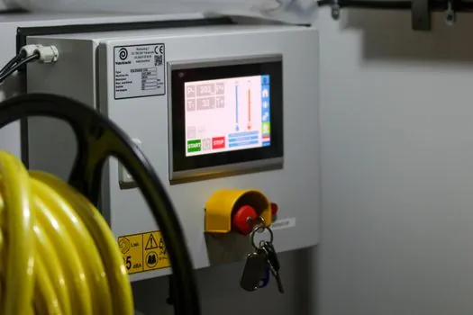
Use a galvanized or plated panel where practical, establish noise zones before routing power and control wiring, and keep high-frequency switching conductors away from sensitive signal circuits [S3]. The installation checklist in MOTION-AT004A-EN-P includes panel material, noise-zone establishment, high-frequency bonding, system-component installation, cable installation, contact-switched-load suppression, leakage current, isolation transformers, and component and wiring noise-zone classifications [S3].
Use short, large-conductivity-area bonding conductors rather than long or small-diameter wires.
For cabinet motion hardware, attach the required hardware to the cabinet door, drawer boxes, and drawer fronts in the specified sequence. Barker Cabinets lists attachment of hinges to cabinet doors and drawer fronts to drawer boxes among the installation steps [S5]. Do not improvise drilling positions or substitute fasteners without checking the applicable product instructions.
Install grounding, shielding, cables, and protective devices
Install the protective-earth connection before energizing the drive, then bond the drive, motor, and intended equipotential surfaces using short, low-impedance high-frequency paths. Rockwell states that bonding conductors create an equipotential level at high frequency, whereas ground conductors route unexpected dangerous chassis currents and voltages to earth; the two functions are not interchangeable [S3].
Route power, motor, feedback, and control cables according to the noise-zone plan, use the specified shielded cables, and terminate shields as directed by the drive and motor manuals. Keep feedback wiring separate from switching-power conductors. Check connector retention, conductor strain relief, cable bend radius, and separation from interference sources before closing the cabinet.
Rockwell recommends addressing contact-switched loads, leakage current, and isolation transformers during installation rather than after intermittent faults appear [S3]. The manufacturer also cautions that an open safety circuit can disable motor torque, while a shorted safety circuit is not an acceptable substitute for a properly designed safety function [S2]. Do not bypass, defeat, or substitute an interlock without a documented risk assessment and the applicable safety design.
Commission from low energy to controlled motion
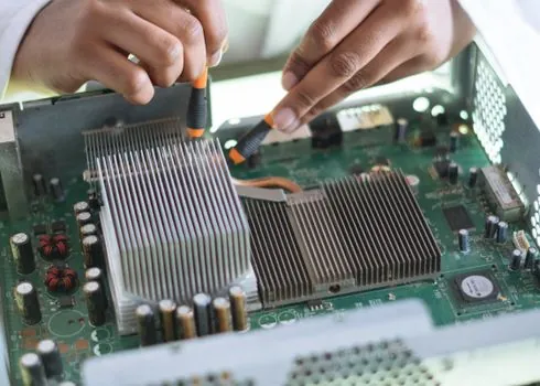
Begin commissioning with the mechanical load disconnected or placed in a safe test condition, then verify input power, control voltage, motor phase wiring, feedback direction, emergency-stop function, and drive fault status. A 0.1 or 1 ohm reading from a digital multimeter does not demonstrate acceptable high-frequency bonding because resistance checks at 50 or 60 Hz do not represent the 100 kHz–10 MHz behavior discussed in the installation guide [S3].
After static checks, perform controlled low-speed motion, increase speed in defined stages, and verify commanded direction, velocity tracking, positioning repeatability, stopping behavior, and fault recovery. Hold each stage long enough to detect abnormal heating, noise, vibration, and EMI-related input instability. Stop escalation if the drive reports a fault, the motor exhibits unexpected movement, or a safety device responds.
Where commissioning depends on correct motor current, encoder type, and feedback resolution, use the Servo Drive Spec Checklist before parameter entry. The acceptance test should record drive model, motor model, feedback configuration, input supply, loaded speed, fault history, and results of all safety checks.
Diagnose installation faults by symptom and cause
For intermittent resets or unexplained input changes, suspect EMI or an equipotential difference before changing motor parameters. The primary control-signal risk band is 100 kHz–10 MHz [S3]. Reopen the cabinet, compare the actual cable route and shield termination against the approved layout, verify short bonding paths, and separate contact-switched loads from sensitive wiring.
For a motor that does not respond, confirm that the drive reports normal supply and motor state, then verify control enable, fault reset, connector seating, phase identification, and feedback recognition. Replace a damaged connector or cable rather than repairing conductors with an unidentified splice. Escalate unexplained faults to the drive or motor manufacturer when the wiring and documentation checks pass.
For abnormal motion, incorrect direction, or unstable positioning, first inhibit the mechanism and verify encoder type, feedback resolution, motor parameters, and feedback polarity. Do not repeatedly reset and retry a runaway axis. Correct the configuration or mechanical feedback mapping, then repeat the low-speed test.
For cabinet motion that moves incorrectly or binds, distinguish mechanical interference from drive commissioning. SERVO-DRIVE uno is specified for installation in a few steps without electrical knowledge [S6], while the drawer and lift documentation specifies compatible systems and mounting sequences [S2][S4]. Replace incorrectly positioned or incompatible hardware and escalate binding conditions that remain after geometry and fastener checks.
Approve the installation with documented evidence
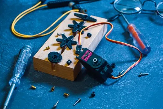
Final acceptance should include the installed drive and motor model, confirmed supply data, motor and feedback compatibility, protective-earth and bonding checks, completed safety-circuit tests, low-speed direction test, loaded-motion test, and a fault log with no unexplained alarm. For the broader industrial context, retain product manuals and applicable safety documentation with the commissioning record, as the best-practice guide explicitly does not replace manufacturer instructions [S3].
For SERVO-DRIVE products, retain the applicable installation instructions and verify the cabinet assembly against the supported lift systems listed in the document. Track two signals after handover: drive fault counts and motor or cabinet temperature rise. Any recurring alarm, unexplained reset, or abnormal heat pattern should trigger a maintenance review rather than an automatic reset cycle.