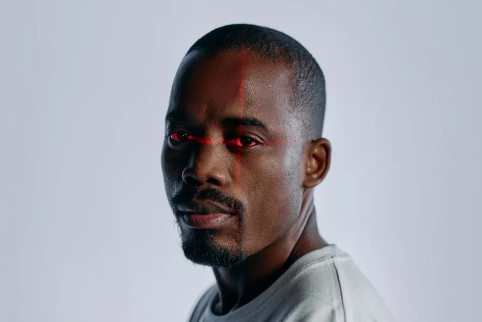
A structured light 3D scanner projects coded white or blue LED patterns over a part and resolves depth from the pattern's distortion with stereo cameras, which is why it captures full-field geometry in a single exposure rather than sweeping a point or line across the surface [S6][S8]. A laser 3D scanner resolves depth by timing or triangulating a coherent laser line or point, with the laser either swept mechanically or fanned into multiple parallel lines for faster coverage [S2][S3].
The two families cover roughly the same part of any 3D scanner buyer's shortlist, but they separate cleanly by working distance, lighting tolerance, and material: structured light is close-range, high-density, color-textured, and light-fragile; laser scanning is longer-range, monochromatic, and tolerates dark, glossy, or metal surfaces that confuse projected patterns [S1][S2][S3].
Working Principle and What Each Method Actually Measures
Structured light scanning is a full-field, area-based optical method: the projector flashes a sequence of stripe, grid, or coded patterns, two or more cameras observe the deformed pattern, and a triangulation algorithm reconstructs dense 3D points across the whole patch in one shot [S6][S8]. Because depth is solved by stereo geometry between known projector and camera baselines, the working volume is short, typically a few hundred millimeters up to roughly 1 m on most handheld units, with sub-0.1 mm point spacing on small parts [S6][S2].
Laser scanning is a point or line-based method: a laser diode emits a coherent beam, the system records the returning light either by triangulation against a 2D sensor or by time-of-flight, and a galvanometer or rotating mirror sweeps the beam to build a surface [S2][S3]. Multi-line laser scanners stack 50 to over 100 parallel lines to recover coverage speed without sacrificing the laser's tolerance to ambient light, dark plastics, and bare metal [S2].
Decision Criteria: Range, Accuracy, Speed, Lighting, Material
Range: structured light is built for short stand-off distances, while laser/LiDAR systems scale to tens of meters and remain the default for building exteriors, plant walkdowns, and topographic capture [S2][S3]. A structured light scanner on a tripod will give up well before a laser scanner on a long baseline reaches its working limit.
Accuracy and density: structured light typically delivers higher local point density and finer geometric detail per pass, which is why it dominates dental, jewelry, and small mechanical part inspection [S6][S2]. Laser scanners trade some local density for range and for stability on geometrically simple, large targets, where their lower per-point noise over distance becomes the deciding factor [S1][S2].
Speed: structured light captures full frames per projection and finishes a part in seconds to a few minutes on handheld units [S6][S8]. Multi-line laser scanners approach similar coverage rates on mid-sized parts but require part-to-sensor motion or scanner motion that structured light avoids, which is why structured light is often preferred for static benchtop inspection [S2][S4].
Lighting tolerance: structured light is degraded by direct sunlight, strong ambient IR/visible light, and reflective or transparent surfaces because the projected pattern is drowned out or specularly reflected away from the cameras [S2][S6]. Laser-based systems, including LiDAR, are markedly more robust outdoors and on dark, glossy, or partially transparent parts, since the monochromatic, narrow-band return can be filtered against broad-spectrum background [S2][S3].
Material and surface: structured light can struggle on shiny metals, clear plastics, and very dark substrates without spray coating; laser scanners handle bare metal, machined steel, cast iron, and dark composites with minimal preparation [S2][S4]. Conversely, structured light captures surface color and texture in the same pass, producing photorealistic models, while laser output is usually a pure point cloud without RGB [S3].
Side-by-Side Comparison on Four Buying Criteria
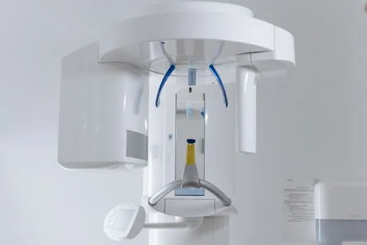
On the four criteria that drive purchase decisions, structured light and laser scanning line up as complementary, not competing: structured light wins on close-range detail and color capture; laser scanning wins on range and material robustness. Per the manufacturer comparison material, structured light "excels in capturing intricate details with speed" while laser scanning "proves efficient for large-scale objects and diverse environments" [S1], and structured light is described as "optimized for close-range, high-density surface reconstruction" while laser systems are "designed for precision-driven industrial work" over a wider working envelope [S2].
For a buyer weighing these options, the practical read across the four criteria is: structured light is the right tool for parts under roughly 1 m, controlled lab or shop-floor lighting, and any workflow that needs color-mapped meshes such as 3D scanner output for dental CAD, heritage, or visual inspection; laser scanning is the right tool for anything beyond a few meters, for outdoor or shop-floor conditions, and for dark, reflective, or transparent parts where projected patterns wash out [S1][S2][S3].
Who Each Technology Is For (and Who It Is Not)
Structured light is for: dental and orthodontic labs, jewelry and small mechanical part inspection, reverse engineering of consumer products, cultural heritage digitization, full-body scanning, AR/VR asset creation, and any QA workflow that needs photorealistic, color-mapped meshes under controlled lighting [S6][S2]. It is not for: outdoor topographic survey, automotive or aerospace exteriors at full vehicle scale, large civil structures, and any object that cannot be brought into a controlled-light booth or coated with a matting spray [S1][S2][S3].
Laser scanning is for: industrial plant and facility as-built capture, automotive body-in-white inspection, aerospace large-part metrology, shipbuilding, construction BIM, topographic and corridor mapping, and any task where a dark, oily, or shiny metal part must be digitized without surface preparation [S2][S3]. It is not for: high-fidelity color capture, or micro-feature inspection where sub-0.05 mm point spacing and RGB texture are required [S3]. Hybrid workflows that mesh structured light for detail zones with laser scanning for global geometry are common on mid-sized industrial parts [S4].
Use Cases, Failure Modes, and Field Realities

A failure mode engineers encounter often with structured light is pattern dropout on shiny or transparent parts: the projected fringe either specularly reflects into the camera as a saturated hotspot or passes through clear plastic and never returns, producing holes in the mesh that must be filled in software or by re-scanning with spray coating [S2][S6]. Another is ambient-light saturation outdoors, where sunlight overpowers the projector's narrowband LEDs and reduces effective working distance to a fraction of the rated spec [S6].
Laser scanners fail differently: on highly specular, mirror-like surfaces the laser can bloom or skip, and on very dark, light-absorbing materials at grazing angles the returned signal can drop below the detector's noise floor unless the system uses a high-power pulsed laser or a long integration time [S2][S3]. Multi-line and time-of-flight LiDAR systems mitigate both with higher pulse energy and matched filters, but they still benefit from surface preparation on glass and chrome [S3].
One representative industrial workflow is reverse engineering a cast aluminum housing: a structured light scan delivers the dense, color-mapped mesh that drives CAD surfacing inside a few minutes, while a laser scan on the same part is faster to set up in a noisy shop but produces a texture-less point cloud that takes longer to surface [S4][S5]. For QA of an injection-molded plastic enclosure, structured light is the default; for QA of a welded steel chassis on the production line, laser is the default. The two are routinely complementary rather than substitutable on a modern metrology bench [S2][S4].
Standards, Sourcing Notes, and Selection Signals
Buyers should anchor selection to verifiable working-volume, accuracy, and point-spacing numbers on the vendor's published spec sheet, since these three figures determine whether a structured light scanner is fit for a given part size; optical non-contact metrology practice is documented in the VDI/VDE 2634 series for optical 3D measuring systems, which defines acceptance and reverification tests for area-based and line-scan optical systems, though the specific revision applied should be confirmed with the supplier [S2][S6]. For laser-based long-range capture, deliverables are typically specified against local coordinate accuracy at given ranges, color-agnostic point density, and registration error across scan stations [S1][S3].
Trackable signals for any 3D scanner purchase in the second half of 2026: (1) the published working-volume envelope and the test target (typically a sphere or gauge block) used to derive the accuracy spec; (2) the stated point spacing at the rated stand-off distance, since density falls with the square of range; (3) the supported export formats and direct CAD/meshing pipelines (STL, PLY, OBJ, and CAD-native via plugins), which decide whether the scanner slots into an existing reverse-engineering or inspection workflow [S2][S4]. A pilot scan on the worst-case real part, with surface preparation explicitly excluded, is the cleanest single signal that a scanner will actually perform in production.
Spec-level background on the components involved: industrial barcode scanner.
Background reading: Industrial Camera Price and Cost Guide: 2026 Tier Map.