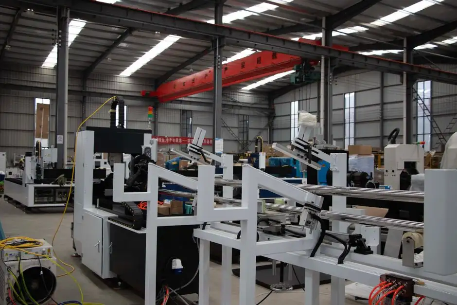
For high-frequency bearing fault detection, the sensor mounting interface is the single largest variable the user controls: a poorly mounted accelerometer will attenuate or ring at exactly the frequencies (typically 20 kHz to 50 kHz and above for envelope analysis) where bearing impact signatures live [S2][S5][S7].
The two-pole magnet versus stud debate, adhesive pads versus wax, and handheld probe shortcuts all come back to one engineering question: what is the usable frequency range the user actually needs, and at what shaft speed is the bearing running? Get the mount wrong and no amount of envelope analysis, spectral kurtosis, or CNN classifier will recover the impact [S4][S7].
Why Mounting Resonances Sit Exactly Where Bearing Faults Live
Localized defects on the outer race, inner race, rolling element, or cage excite structural resonances in the bearing and surrounding housing each time the rolling element strikes the spall, and the high-frequency content of those impacts carries the diagnostic information (BPFO, BPFI, BSF, FTF) needed for envelope demodulation [S4].
The mounting interface is itself a mechanical system with a natural frequency; two-pole magnets on curved housings, magnetic bases on painted or non-ferrous surfaces, and adhesive pads with a soft bond layer all push that interface resonance down to a few kHz, which means impact energy above 10-20 kHz is filtered out before it ever reaches the charge amplifier [S7]. A properly torqued stud on a flat, machined, degreased surface keeps the mount resonance above the accelerometer's own resonance and preserves the 20-50 kHz band that is the working range for early-stage bearing defect detection [S2][S7].
Reviewer guidance from maintenance publications is blunt on the subject: two-pole magnets are flagged as "not ideal mounting" for any high-frequency capture, while a flat magnet base or, better, a stud is the minimum acceptable configuration [S7]. For more on bearing construction and failure modes, the ball bearing reference page covers the geometry the formulas in the next section rely on.
Comparison of Mounting Methods Against Decision Criteria
The four commonly available mounting options line up as follows on the criteria that actually drive a high-frequency bearing fault detection program: usable frequency range, repeatability, surface preparation, and risk of transducer damage. [S2]
Stud mount (e.g. 10-32 or M5 stud through a tapped, flat surface, torqued to manufacturer spec): the reference configuration. Highest usable frequency range, typically 1/3 to 1/5 of the accelerometer's specified resonance, so a 100 kHz sensor stays useful to 20-30 kHz in practice; excellent amplitude and phase repeatability; requires a machined flat spot and tapped hole, which is the main engineering objection [S7]. Adhesive mount (cyanoacrylate or epoxy pad): usable to roughly 5-10 kHz depending on bond stiffness and cure, useful where tapping is impossible, but the bond layer is the resonant element and its temperature rating is the real limit [S7]. Two-pole magnet: usable only to the low kHz range, suitable for low-speed machinery health trending, not for early bearing fault detection [S7]. Flat magnet base / magnetic pad with a broader footprint: a meaningful step up from the two-pole design, but still not a substitute for a stud in high-frequency work [S7]. Handheld probe: convenience only; the operator's hand damping makes the result qualitative at best and is generally excluded from any formal high-frequency bearing condition monitoring campaign [S2][S7].
For low-speed machinery in particular, the high-frequency technique depends on capturing the structural resonance excited by each impact, and that is precisely the energy a magnet or adhesive will not transmit [S2].
Shaft Speed, Bearing Geometry, and Where the Fault Frequencies Actually Fall
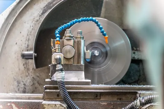
BPFO, BPFI, FTF, and BSF are not integer multiples of shaft speed, and that non-integer relationship is what lets a vibration analyst separate a bearing defect from unbalance or misalignment, which sit at 1x and 2x shaft speed [S2].
The four primary fault frequencies used in envelope analysis are calculated from shaft speed (f_r), number of rolling elements (n), ball diameter (d), pitch diameter (D), and contact angle (phi): BPFO = n/2 * f_r * (1 - d/D * cos(phi)); BPFI = n/2 * f_r * (1 + d/D * cos(phi)); FTF = f_r/2 * (1 - d/D * cos(phi)); BSF = D/(2d) * f_r * (1 - (d/D * cos(phi))^2) [S2][S4]. For a typical 6205 deep-groove ball bearing with roughly 9 balls, these faults sit between 3x and 8x shaft speed, so on a 1,500 rpm (25 Hz) induction motor the impacts are still in the low kHz; on a 50 Hz shaft, an inner-race fault can fall near 200 Hz, well below the mount resonance, and even a magnet can carry the signal [S2].
Once the fault frequency and its harmonics are above roughly 10 kHz, the engineer is forced into the high-frequency resonance region of the bearing-housing system, and the mounting method becomes a hard requirement, not a preference [S2][S4].
When the Mount Is the Sensor, and When to Switch Techniques Entirely
Induction motor bearing failures account for more than 40% of motor failures in published surveys, compared with roughly 10% for rotor faults, so the bearing is where the maintenance budget is justified to spend on a stud [S1].
For very low-speed machinery, or where a stud cannot be installed, ultrasound (typically 30-80 kHz airborne or structure-borne) and the high-frequency vibration techniques (Spike Energy, Shock Pulse, PeakVue) are the fallback, because they are designed to capture the impact events directly rather than demodulating a structural resonance [S8]. Acoustic emission, ultrasound, and oil-analysis wear particle counts each address a specific failure-mode window: AE catches crack initiation before spalling, ultrasound catches the first metal-to-metal impact, and oil analysis catches the wear debris that follows [S8][S10]. A complete condition-monitoring program therefore layers these with vibration rather than choosing one over the other [S5][S8].
For AI- and ML-driven diagnostic pipelines, the same mounting discipline applies: a ResNet-50-SVM hybrid trained on the CWRU dataset has been reported at 95.51% classification accuracy, but the features feeding the model only exist if the impact energy actually reached the sensor, which is a mounting problem before it is an algorithm problem [S1].
Field Practice: Cabling, Grounding, and the Bits That Defeat a Good Mount
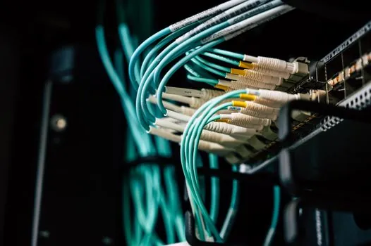
A stud mount is necessary but not sufficient: low-noise cabling, proper strain relief, and a clean electrical ground are the next three failure points, and any of them will smear the high-frequency content the mount was carefully set up to capture [S5].
In practice, the field checks are: torque the stud to the accelerometer vendor's spec, not "tight enough"; grind the contact pad flat to better than 0.05 mm and clean it with a degreasing solvent before mounting; verify with a tap test (or a shaker, where available) that the mount resonance sits above the bearing impact band; use a low-noise coaxial cable and avoid routing it parallel to VFD output cables, since the VFD output common-mode can inject switching noise into the accelerometer amplifier [S2][S5]. On machines fed by a variable frequency drive, an additional order-tracking step in the pre-processing chain is normally required because the shaft speed is no longer constant [S4].
Temperature and oil analysis remain the corroborating channels, since prolonged operation above roughly 125 degrees C is the rule-of-thumb threshold above which bearing life shortens noticeably, and a bearing that is failing mechanically will usually start shedding debris before the vibration signature crosses the alert threshold [S5].
Track the next two signals: any revision of the ISO 15243 bearing damage classification that explicitly references high-frequency detection methods, and the CWRU and MFPT dataset updates that machine-learning vendors use to benchmark their classifiers, because both set the de facto floor for what the on-machine mount has to deliver [S1][S4][S9].
For component-level specifications, see gas detection.
Background reading: CE technical file for machinery: what Annex VII actually requires in 2026.