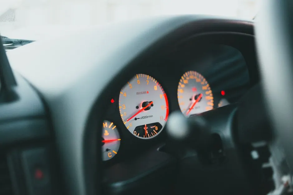
A tachometer is specified by its measurement duty, not by brand: the seven criteria that drive a defensible pick are speed range, sensor mounting, output signal type, accuracy class, environmental rating, hazardous-area certification, and the mechanical/electrical interface to the PLC or display.
For rotating machinery above 60 rpm, a non-contact optical or magnetic pickup avoids shaft wear and survives IP65 wash-down duty; below 60 rpm, a Hall-effect or encoder-based tachometer is the practical floor because pulse-per-revolution counting becomes unreliable at sub-Hz shaft speeds.
Speed range, resolution, and pulse-per-revolution count
The first numeric gate is maximum shaft speed: most industrial non-contact tachometers carry an upper limit between 10,000 rpm and 50,000 rpm, with optical reflective units typically rated 100 to 30,000 rpm at a sensing distance of 50 to 300 mm, while magnetic pickup heads are commonly used in the 1 to 10,000 rpm range at 0.5 to 5 mm gap. Resolution scales with the number of pulses per revolution (PPR): a 60 PPR target yields 1-degree mechanical resolution, a 360 PPR encoder yields 0.1 Hz resolution at 1 rpm, and a 1 PPR reflective mark is adequate for process speed indication but inadequate for servo-loop feedback. [S4]
Engineers specifying overspeed protection should size for at least 20% headroom above the maximum operating rpm, because inductive pickups drift in output amplitude above their calibrated band and can miss pulses under excessive run-out.
Sensor mounting: contact, non-contact, and shaft-coupled options
Contact tachometers (mechanical, wheel-on-shaft) remain in use for handheld RPM checks on belt-driven equipment where access is easy, but they introduce slip error of 1% to 3% and wear the wheel every 1,000 to 5,000 hours of use. Non-contact optical (visible red, 660 nm) units read a reflective mark at 10 to 150 mm standoff and are the default for lab and field service, while non-contact magnetic units read a toothed wheel or a ferrous keyway at 0.5 to 5 mm gap and are preferred on oily, dirty, or steam-washed surfaces where optical contrast is unreliable. [S1]
For permanently installed service on motors, a shaft-coupled encoder with a flexible bellows coupling handles 6,000 to 12,000 rpm continuous duty and survives misalignment up to 0.2 mm radial and 1 degree angular. Where the shaft end is inaccessible, a through-bore or hollow-shaft encoder mounts directly on the driven shaft, eliminating the coupling and the alignment stack.
Output signal: analog, pulse, and fieldbus

Output selection is dictated by what the downstream device expects: a 4-20 mA analog loop is the standard for a flow meter or pressure transmitter style readout into a DCS analog input card, and it is typically scaled across 0 to maximum rpm; an NPN/PNP open-collector pulse output feeds a digital counter or PLC high-speed input and is the cheapest path for overspeed trips; a 0 to 10 V analog output is common on European drives; an RS-485 Modbus RTU output lets a single cable daisy-chain 32 devices on one trunk for multi-pump stations. [S1]
For hazardous areas, the output must match the barrier: a 4-20 mA loop sits behind a galvanic isolator or Zener barrier under ATEX 2014/34/EU, while a Modbus RTU line needs a certified RS-485 intrinsically safe interface. Mixing 24 V encoder power and signal on the same cable is acceptable only when the cable shield is grounded at one end and the manufacturer documents the combined cable spec.
Accuracy class, repeatability, and update rate
Industrial tachometer accuracy is stated as a percentage of full scale or of reading: a typical process-grade optical unit carries plus or minus 0.05% of reading plus plus or minus 1 digit, while a handheld contact unit may carry plus or minus 0.5% of full scale. Repeatability is usually a tighter number, around 0.02% of reading, and matters more than absolute accuracy for closed-loop speed control. [S1]
Update rate is a separate spec and is often the bottleneck in vibration-prone service: a 100 ms refresh gives 10 Hz display bandwidth, which is fine for trend logging but too slow for a paper-machine reel that needs 1 kHz update to capture web tension events. A stroboscope-style tachometer sidesteps the update problem by holding the apparent image steady, at the cost of needing a stable reflective mark and a darkened viewing area.
Environment, ingress protection, and temperature
Ambient temperature is the most common reason a tachometer fails in the field: optical sensors rated 0 to 50 degrees C are typical, while industrial units rated minus 20 to plus 80 degrees C cover most outdoor motor enclosures; bearing-housing mounting on a hot pump pushes the requirement past 100 degrees C, and the sensor head must be remote-mounted with a fibre-optic light guide. Ingress protection should be selected to match the cleaning regime: IP65 handles hose-down, IP67 handles temporary immersion to 1 m for 30 minutes, and IP69K handles high-pressure, high-temperature wash-down in food and pharmaceutical lines. [S1]
Vibration resistance is rarely listed as a number but is implied by the housing: a potted stainless-steel body survives 10 g RMS at 50 to 500 Hz on a motor frame, while a plastic-bodied handheld unit should be kept below 2 g RMS. Chemical compatibility of the lens is a frequent miss: polycarbonate windows craze in the presence of ketones and aromatic solvents, so acrylic or glass windows are required for paint-line or refinery duty.
Hazardous-area and certification fit
European chemical and refinery builds route tachometer selection through ATEX 2014/34/EU: Zone 1 typically demands Ex d (flameproof) or Ex e (increased safety) with a tacho rated to EPL Gb, while Zone 2 accepts Ex nA non-sparking. North American projects use the NEC Class/Division system: Class I Div 1 requires explosion-proof enclosures, while Class I Div 2 accepts non-incendive (NI) field wiring. IECEx certification is increasingly accepted in parallel with ATEX for global EPC work.
A practical mistake is to specify an IP67 encoder with a tacho-rated certification; the certification, not the IP rating, governs explosive atmospheres. A second mistake is to chain a non-IS analog output through a generic cable gland; the gland must carry its own Ex d or Ex e marking matching the enclosure.
Mechanical interface, cable, and integration
The mechanical interface is the last spec to fix and the first to fail: a 10 mm shaft with a flat, an 8 mm hollow bore, and a 6 mm through-bore are three different products that share no common bracket. Cable specification is equally binding: a drag-chain rated cable survives 10 million flex cycles, while a standard PVC cable fails in 100,000 cycles on a robot axis. For a pressure sensor family install, the same cable type is often shared between the tacho, the pressure transmitter, and the flow meter, which keeps spare parts inventory lean. [S1]
Compare four realistic options on a single line: an optical handheld (cheap, 100 to 30,000 rpm, 0.05% of reading, no installation); a magnetic pickup (1 to 10,000 rpm, IP67, suited to dirty shafts, requires ferrous target); a shaft-mounted encoder (up to 12,000 rpm, 0.02% reading, quadrature output for direction sense, needs alignment); a hazardous-area tacho (ATEX Ex d IIB T4, 4-20 mA output, priced 3x to 5x standard, 4 to 6 week lead). Pick the magnetic pickup when the shaft is dirty and accessible; pick the encoder when the loop needs direction; pick the ATEX unit when the area classification demands it; avoid the contact wheel when the duty is continuous, because wheel wear dominates the maintenance cost.
Final shortlist logic: lock the speed range and PPR first, fix the output and certification next, then close on the mechanical interface, and only then evaluate brand and lead time. A 5 minute cross-check on the magnetic level gauge selection map shows the same spec-first discipline applied to chamber material and float density, and the same approach carries directly across to turbine flowmeter selection, where the pulse-output wiring rules mirror the tacho analog path. The signal lands on the same PLC high-speed counter, the same cable spec, and the same hazardous-area barrier family, so a coherent parts list is the audit trail that survives a turn-over.