
Standard mold bases in the LKM, HASCO, DME, and PCS catalogs are the default starting point for telecom-enclosure tooling, and are typically offered in 2-plate or 3-plate configurations with single or multi cavities (1×1, 1+1, 1×2, 1+1+1 layouts) per the TPI product reference [S1]. For indoor router and switch housings, a 1×1 single-cavity 2-plate base is the common baseline; for outdoor antenna and CPE housings, a 1×2 or 1+1+1 layout in a 3-plate base is more typical because cold-runner balance becomes harder as projected area grows past roughly 300 cm².
Telecom-enclosure wall sections are thin, typically 1.5–3.0 mm, so the mold base's plate stack and guide system carry most of the clamp tonnage rather than the cavity inserts. That is why the mold base selection, not just the cavity steel, is the dominant cost and lead-time variable on a telecom housing tool.
Steel Grade and Plate Hardness for Telecom Cavities
For telecom enclosures in ABS, PC, and PC/ABS, A-plate and B-plate inserts are routinely cut from P20 (1.2311, pre-hardened to roughly 30–32 HRC) or 2738 (1.2738, pre-hardened to roughly 32–34 HRC), with the cavity pocket depth sized to the part's maximum draw depth plus 15–25 mm of backing steel [S2]. P20 is the default for production runs under 500,000 shots when the resin is ABS or filled PC/ABS, and 2738 is specified when the same tool is expected to run glass-filled grades for stiffness or for elevated service temperatures inside 5G small-cell radio housings.
Standard mold base frames are usually supplied in S50C (1.1730, roughly 50 HRC after stress-relief) for the clamp plates, A/B plates, and support plate, with guide pins and bushings in SUJ2 (1.3505, 58–62 HRC) or equivalent through-hardened bearing steel [S2]. Hardened leader pins are the single most specified wear item on telecom tooling: any loss of guide alignment shows up as wall-thickness variation on the enclosure, which then drives Wi-Fi antenna pattern shift on the finished product. For abrasive glass-filled resins, a wear plate at the parting line is a common add-on.
Aluminum standard bases (for example, 7075-T6) are also sold by PCS-style catalog suppliers, with 9 frame sizes from 08/08 to 12/16 and A/B plate thicknesses between 1.94" and 3.44" (roughly 49.3–87.4 mm) [S5]. Aluminum bases cut machining time and weight, but are not appropriate for glass-filled or flame-retardant compounds above roughly 30% filler loading because galling and cavity wash appear within a few thousand shots.
Frame Size, Clamp Tonnage, and Projected Area
Frame size must be selected from the part's projected area, not from the part's footprint, because the runner system, sprue, and any 3-plate cold-runner plate add 20–40% to the actual mold footprint on telecom tooling. A practical sizing rule is projected area × 4–5 t/in² (roughly 0.6–0.8 t/cm²) of clamp force; a 200 cm² router housing therefore needs a press in the 120–160 t range, and a 400 cm² outdoor CPE housing needs 250–320 t [S6].
The mold base selection flow for telecom housings generally starts with: (1) identify part projected area, (2) add 20–30 mm per side for runner and gate access, (3) pick the smallest LKM/HASCO frame that fits the cavity plus runner footprint, and (4) verify the press's tie-bar clearance and platen size accept the base outline [S6]. Under-sizing the frame is the most common cause of flash and short-shot defects on thin-wall telecom parts, because the unsupported mold span deflects under clamp tonnage and lets the cavity open by 0.05–0.10 mm mid-stroke.
Resin Match: ABS, PC, PC/ABS, and Glass-Filled Grades
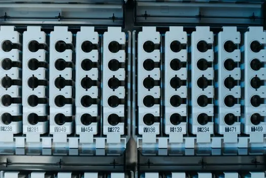
ABS, PC, PC/ABS, nylon (PA), and PBT are the polymers most commonly specified for injection-molded electronic enclosures, with ABS used for cost-sensitive indoor housings, PC for impact- and heat-critical parts, PC/ABS for the laptop/consumer-grade middle ground, and nylon or PBT for connectors and wear-loaded features [S3]. For 5G small-cell radio housings, glass-filled PC/ABS (typically 10–20% glass) and flame-retardant grades to UL 94 V-0 are the dominant specs; for indoor ONT/router shells, unfilled ABS or PC/ABS without a flame rating is still common.
Resin choice sets the mold base decision tree in two places: drying and shrinkage. Nylon requires pre-mold drying at roughly 80–120°C for 4–8 hours and shrinks between 1.2–1.8% in the flow direction, which forces a larger A-plate cavity pocket and a stiffer support plate; PBT shrinks in a similar 1.4–2.0% band and is abrasive on the cavity surface [S3]. ABS and PC/ABS are more forgiving, with shrinkage around 0.4–0.7% and 0.5–0.8% respectively, so the standard LKM/HASCO base dimensional tolerances are usually adequate without re-cutting the pocket.
Resin behavior is also why the mold base is treated as a separate procurement line from the cavity steel: changing the resin family (for example, ABS to glass-filled PA) usually forces a re-evaluation of the A-plate and the ejection system, even when the frame size and clamp tonnage stay the same. The broader injection mold and casting mold family is covered separately for higher-temperature and metal-mold workflows.
Cavity Layout: 2-Plate vs 3-Plate, and Ejection
2-plate molds with a single parting line are the default for telecom enclosures, because the simple structure is easier to balance, has a shorter cycle, and matches the "simple structure, not-very-strict tolerance" selection case used in standard mold-base catalogs [S6]. 3-plate molds are added when a central gate is required for cosmetic gating on a visible face, or when multiple cavities need to be fed by a balanced cold runner without a hot-runner manifold.
Ejection on thin-wall telecom housings is almost always pin ejection on the B-side, sized so the pin lands on a boss or rib rather than the cosmetic surface; stripper-plate ejection is reserved for transparent parts such as indicator lenses where pin witness marks would fail cosmetic inspection [S2]. Return pins and ejector-pin plate travel must be set so the pins retract fully before the mold closes, otherwise the leader-pin bushing will score within a few hundred cycles.
For more general selection logic that overlaps with telecom tooling, the agricultural-injection mold base selection flow and the mold base selection for pump and valve production write-up cover the same frame-size and hardness logic, and the energy-equipment piece at mold base selection for energy equipment is a useful counter-example for thicker-wall industrial parts.
Standards, Tolerances, and Verification
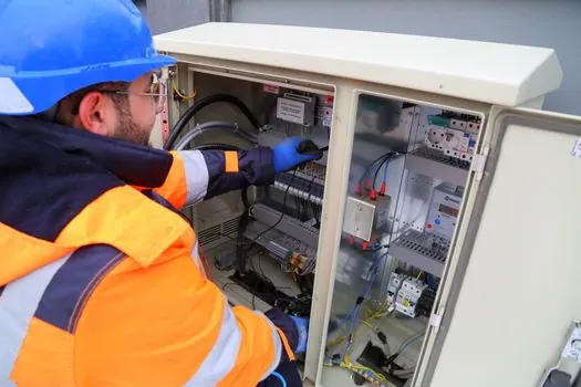
Telecom-enclosure mold bases are not governed by a single telecom-specific ISO or IEC mold-base standard; instead, suppliers hold to the LKM, HASCO, DME, or PCS catalog dimensional systems, and the customer-side telecom equipment standards (for example, IEC 60068 environmental testing on the finished part) are met at the assembly level rather than the mold-base level [S1][S2]. UL 94 V-0 ratings are specified on the resin datasheet, not on the mold base; the mold base only has to produce dimensionally stable, void-free, weld-line-free parts to allow the resin to demonstrate its rating [S3].
Dimensional checks on a delivered mold base follow the LKM/HASCO frame-tolerance tables (typically ±0.02 mm on cavity pocket location, ±0.01 mm on leader-pin-to-bushing fit, and ±0.03 mm on parting-line flatness) [S2]. For telecom enclosures with RF-critical features (antenna windows, waveguide ports), the additional check is cavity-to-cavity shift across the parting line, which is held under 0.02 mm to avoid altering the antenna's radiation pattern. Mold base frame flatness is verified with a granite check and a dial indicator on a 4-corner sweep before any cavity steel is cut.
Limits, Failure Modes, and When Not to Use a Standard Base
A standard catalog mold base is the wrong choice when the telecom part exceeds roughly 600 × 800 mm in envelope, when slide actions exceed 50 mm of travel, when the projected area plus runner pushes clamp tonnage past the press's tie-bar clearance, or when the part needs unscrewing threads in a single shot [S6]. In these cases, a custom base with a larger support plate, additional leader pins at the corners, and dedicated slide-retention blocks is required; the standard catalog frame is not engineered for the deflection and the leader-pin loads that show up on a large-format tool.
Common failure modes tied to mold-base selection on telecom tooling are: (1) flash on the parting line, almost always traceable to a frame that is too small for the projected area, (2) wall-thickness drift across a cavity, tied to leader-pin wear on a high-shot-count base, and (3) ejector-pin witness marks on a cosmetic surface, tied to pin landing on a flat area instead of a rib. The agricultural mold base selection write-up documents the same failure-mode pattern, and the broader comparison of sand-casting mold base vs injection-mold base makes the limits of catalog bases clearer for larger and non-polymer tools.
Verify base flatness at the four corners with a dial indicator before any cavity steel is ordered; confirm the LKM/HASCO frame part number is in production (not a discontinued catalog code) by checking the supplier's current price list dated within the past 6 months. These two checkpoints are the cheapest insurance against a 30–60 day delivery slip on a telecom-enclosure program.