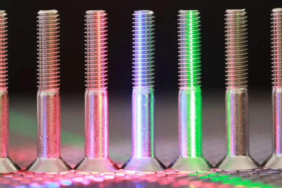
A standard A-series mold base is available in 43 catalog sizes ranging from 7.875 x 7.875 inches up to 23.75 x 35.5 inches, making it the most frequently specified pre-engineered assembly for general-purpose injection tooling [S6]. Plate thickness, plate count, and steel grade drive both rigidity and price: a small 8x8 inch base costs less than a 24x36 inch base because of the raw steel volume, machining time, and handling involved [S5].
Mold bases are specified to support tooling in injection molding, compression molding, and resin transfer molding (RTM) processes, and the plate stack must transfer clamping, injection, opening, ejection, and side-action loads while keeping guide-pillar alignment stable [S1][S4]. In practice, three material families dominate the market: hot-rolled steel, chrome-moly steels, and stainless steel, each chosen for a different wear, polishability, and corrosion profile [S2].
Plate Stack Anatomy and What Each Plate Does
A typical injection mold base consists of a top clamp plate, A plate (cavity retainer), B plate (core retainer), optional support plate, C plate (spacer block), rear clamp plate, ejector pin plate, and ejector retainer plate, with guide pillars, bushings, return pins, and support pillars completing the alignment system [S3]. The C plate spacer block height is tied directly to the part's ejection stroke, while the A and B plates carry the cavity and core inserts that actually form the molded geometry [S3]. A correctly specified mold base controls structural support and machine interfaces; it does not by itself validate cavity geometry, gate performance, cycle time, or part tolerance, all of which require separate engineering input and process validation [S4].
Steel Grade Selection: P20, 1045/S50C, Chrome-Moly, and Stainless
Mold base material breaks down into three working families: hot-rolled steel, chrome-moly materials, and stainless steel, with selection driven by expected production volume, coolant chemistry, and polishability demands [S2]. Within the standard catalog offering, P20 pre-hardened steel is the most common default; for less demanding runs, lower-cost carbon steels such as 1045 or S50C are routinely substituted, and 1.2738/P20+Ni variants appear where higher polishability or throughput is required [S5]. Stainless mold bases (typically 420SS or similar) are reserved for corrosive resin processing, medical or optical applications, or where the base itself doubles as a contact surface.
Standard Catalog vs Custom Mold Base: A Criteria Comparison
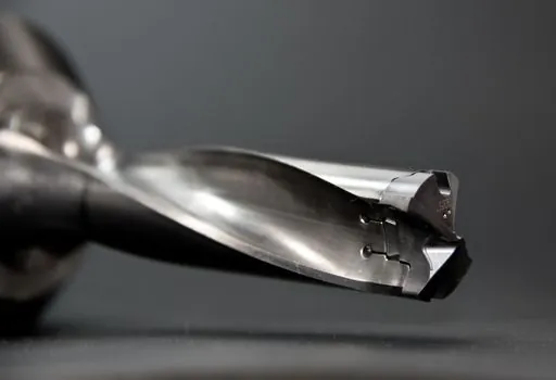
Standard mold bases offer shorter delivery times, ready-to-machine reference geometry, and predictable cost, while custom bases are sized to the released cavity layout, remaining steel section, insert fastening, and maintenance access requirements [S3][S4]. The decision map below lines the two options up against four selection criteria.
Standard catalog bases score well on lead time (typically days to two weeks), spare-parts availability, and unit cost, but constrain plate thickness, locating-ring size, and ejector interface to supplier-fixed patterns [S5][S6]. Custom bases win on press-fit (locating ring, sprue bushing, nozzle radius, clamp slots, mold thickness, and ejector interface can all be matched to the receiving plant's target press) and on remaining steel section around large insert pockets, but cost more and extend lead time by weeks [S4].
For prototype or low-volume runs under 10x12 inches, an off-the-shelf A/B-plate standard base in P20 or 1045 at $500 to $1,500 is the rational pick [S5]. For production tooling at 18x24 inches or above, or where a multi-plate stack with stripper or support plates is required (DME #3, #5, or #7 styles), the same source places expected cost at $1,500 to $5,000 for standard configurations and higher for custom layouts [S5]. Plate material, flatness, remaining load-bearing sections, guide fits, fastener engagement, and assembly clearances must be verified against the released drawings, material specifications, and inspection plan before the base is accepted [S4].
Sizing, Calculation, and the Insert Envelope
Mold base sizing starts with the width and length needed to envelope the cavity layout, the number of cavities, the runner and gate area, and the maintenance access requirements around the inserts [S8]. The released layout must retain the project-required steel section around insert pockets while leaving clearance for cooling channels, runner channels, fasteners, and service access [S4]. For the mold base itself, the calculation sequence is to first determine width, then length, then thickness and plate count, with the C-plate spacer block height sized to the part's draw and ejection stroke [S3][S8].
Press Interface and What the Base Does Not Define
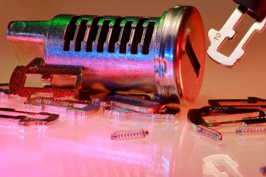
Even a correctly sized mold base must still be verified against the receiving plant's target press: locating ring, sprue bushing, nozzle radius, clamp slots, mold thickness, ejector stroke, and cooling, hydraulic, and electrical connections are all part of the press-interface checklist, and final approval should record the receiving plant, target press ID, and the effective press-interface record [S4]. Designers often overload the base with responsibilities it cannot carry on its own: cavity geometry, molded-part tolerances, gate and cooling performance, cycle time, the process window, and mold-trial acceptance all sit outside the base's scope and require separate engineering calculations, released acceptance criteria, and production-validation evidence [S4].
Lifecycle Cost: Why the Cheapest Quote Is Rarely the Best
Choosing a mold base is a balance between initial purchase price and long-term operating cost; a cheaper base that needs frequent maintenance, produces higher scrap rates, or fails early will exceed the savings within the first production runs [S5]. A small 8x8 inch base buys less steel, less machining, and less handling than a 24x36 inch base, so cost scales with envelope area, plate count, and feature complexity, not with the word "standard" alone [S5]. Specifying a higher-grade pre-hardened steel, more accurate guide fits, or extra cooling-line ports adds unit cost, but those choices are usually recovered through higher yield, longer tool life, and reduced downtime over the mold's service life [S5].
Selection Signals Worth Tracking

Forthcoming tooling decisions on hardware lines should track three verifiable signals: the released press-interface record naming the target press ID and receiving plant, the documented remaining steel section around large insert pockets on the approved base drawing, and the steel-grade callout on the purchase order, since P20, 1045/S50C, and stainless selections imply very different service-life and coolant-compatibility expectations. Related spec-driven selection logic for industrial fluid-power and motion components and for casting tooling geometry follows the same envelope-first, interface-second discipline, and is worth cross-referencing when the same shop runs both plastic injection and metal casting work. For shops scaling up additive-manufactured conformal cooling inserts alongside conventional mold bases, the additive manufacturing material selection map is the natural next read. [S4]
This topic is covered further in Paperless Recorder Suppliers and Manufacturers: 2026 Lineup and Selection Map.