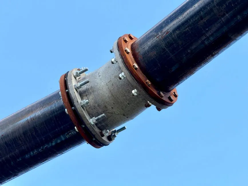
Use a baseline of 10 pipe diameters upstream and 5 pipe diameters downstream of a thermal mass flow meter, then increase clearance when fittings disturb the flow profile.
This guide covers insertion and inline thermal mass flowmeters installed in gas lines, including elbows, control valves, reducers, changes of direction, and wet or dry service.
Straight-pipe requirements and the 10D upstream, 5D downstream rule
A thermal mass flowmeter can operate in vertical, horizontal, or angled piping, but the measured flow depends on the velocity and temperature profile reaching the sensing element [S1]. A repeatable profile is required for laboratory accuracy to remain meaningful in the field [S3].
The practical baseline is 10 pipe diameters of straight upstream pipe and 5 pipe diameters downstream [S2].
The distinction between pipe diameters and physical length is important. A DN100 line has a nominal diameter near 100 mm, so 10D upstream is approximately 1,000 mm and 5D downstream is approximately 500 mm. Actual dimensions should be taken from the pipe inside diameter or from the meter manufacturer’s clearance table, because nominal bore and exact clear distance are not always identical.
How elbows, valves, and reducers change the flow profile
Control valves and pressure-control devices can generate turbulence upstream or downstream, so their stated straight-pipe requirement cannot be separated from the meter requirement [S2]. A reducer also changes both cross-sectional area and velocity distribution. A line that steps from one diameter to another immediately beside the meter does not provide the same flow condition as uniform-bore straight pipe.
Use this comparison when laying out a run:
Physical clearance above valves and accessible installation space
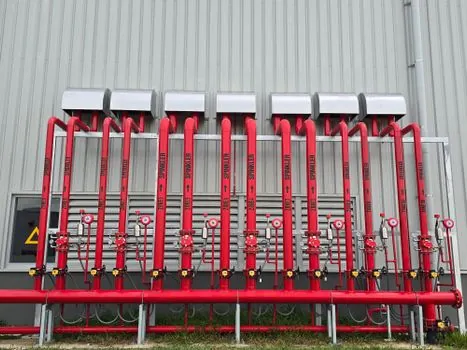
One insertion-meter installation manual specifies approximately 30–36 in. of clearance from the pipe wall to the nearest obstruction above the valve assembly [S7]. That dimension is physical access space for inserting and removing the probe, not straight-pipe flow clearance and not a substitute for 10D/5D.
Separate the two requirements on the installation drawing. Dimension A is flow-development length from the disturbance to the meter. Dimension B is service access above the valve or meter. Dimension C is insertion-tool clearance and probe withdrawal depth. A drawing that shows only the physical space available for maintenance can still leave the flow profile inadequate.
For an insertion instrument, position the sensor at the pipe centerline and follow the installation-depth chart for the selected probe and pipe size [S6]. This distinction matters because the natural selection reference for this decision is a thermal mass flowmeter, not a generic flow meter.
Orientation, gas effects, and other installation constraints
On horizontal gas piping, side-of-pipe installation is recommended, while installation directly above the pipe is discouraged because liquid can collect on or affect the sensor [S2]. On a vertical pipeline, when the gas density is higher than air, make sure the flow goes from down to up [S2].
Thermal measurement also depends on gas composition, thermal conductivity, specific heat capacity, moisture, and installation temperature [S1]. The measured value can be affected by fluid properties such as thermal conductivity and specific heat capacity, gas composition in the case of mixtures, and installation conditions [S1].
Confirm the gas, pressure, temperature, flow range, pipe size, orientation, and calibration basis before the meter is released for fabrication.
Commissioning checks for unstable or biased flow
First inspect the physical installation: confirm 10D upstream and 5D downstream for the baseline layout, verify that the sensor is centered for an insertion probe, and check that no valve is throttling immediately adjacent to the meter [S2][S6]. Second, compare the configured gas and temperature compensation against the actual service.
Acceptance criteria must come from the purchase specification and calibration certificate, not from a generic accuracy claim. FCI states that installed accuracy must combine basic instrument accuracy, calibration uncertainty, flow-profile disturbance, and gas and installation temperature effects [S3]. If readings remain unstable after correcting orientation, depth, and compensation, relocate the meter or escalate to the manufacturer rather than widening the clearance pipe without a defined basis.
Acceptance criteria for the final installation drawing
The final drawing should show the meter model, pipe inside diameter, flow direction, meter reference plane, 10D upstream dimension, 5D downstream dimension, every elbow and valve, reducers, branch connections, and physical removal clearance. For disturbed runs, add the meter manufacturer’s required straight-run lengths rather than assuming that 10D/5D remains valid [S2][S4].
Record the operating gas, composition, moisture condition, design pressure, design temperature, minimum and maximum flow range, mounting orientation, insertion depth, and calibration method. FCI’s guidance identifies gas type and composition, clean or dirty service, moisture, and process temperature and pressure as specification inputs that affect expected field performance [S3].
Do not repair a failed installation merely by adding arbitrary spool length. A short spool cannot correct a probe installed off-center, a wrong gas configuration, liquid accumulation above the pipe, or a valve that never reaches its intended opening. Those are installation or configuration faults. If the specified straight lengths cannot be met, obtain a written deviation or relocate the meter before commissioning.
The trackable design record is the approved piping sketch with both flow clearances and maintenance access dimensions, followed by the meter’s actual-gas calibration certificate and commissioning comparison against the reference device.