
Thermal mass flow meters directly measure gas mass flow, and their demand is being shaped by compressed-air accountability, natural-gas management, emissions measurement, and low-power metering.
The technology applies to industrial gases and compressed air, with sensor packages including heated and temperature elements, inline or insertion installations, and 4–20 mA, HART, Foundation Fieldbus, PROFIBUS, and Modbus options [S1][S4].
Direct Mass Measurement Solves Gas-Flow Variability
Thermal mass flow meters determine mass flow from the heat carried by gas molecules, rather than deriving volumetric flow from pipe geometry, velocity, pressure, or temperature [S2][S6]. A heated sensor transfers heat to the gas, a temperature sensor measures the downstream condition, and the transmitter restores a constant temperature differential by adding heat. The required electrical power is proportional to mass flow, which links the measurement to the gas mass passing the probe [S2].
This distinction matters because gas mass is independent of changes in pressure and temperature, unlike a volumetric measurement converted to standard conditions [S2]. For compressed-air networks, thermal mass meters can measure total consumption, allocation between production stations, and leakage that would otherwise remain hidden [S3][S5].
The thermal mass flowmeter reference covers the instrument family in more detail.
Compressed-Air Leakage Creates a Quantifiable Business Case
That estimate applies to compressed-air leakage, not the thermal meters themselves, but it explains why demand concentrates around leakage detection, branch allocation, and consumption reporting.
Thermal mass flow meters can be installed at multiple facility locations to measure compressed-air use and natural-gas consumption at individual combustion sources [S3]. Typical deployments include central headers, production stations, boilers, furnaces, and heaters, where an operator needs to compare actual mass delivery with equipment demand [S5].
FCI documents insertion and inline products from 6 mm pipe size to the largest of stacks [S4]. This range supports a practical distinction: compact insertion probes suit local monitoring, while inline or dual-element instruments suit larger headers and applications requiring spatial averaging [S4].
Energy Management Turns Flow Data Into an Operating Control
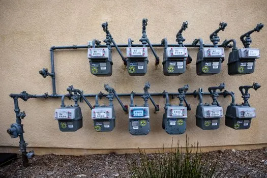
ISO 50001 requires an energy management system to include an energy policy, energy objectives, implementation, and performance monitoring, creating a practical framework for using gas-mass data to manage consumption [S3]. Thermal mass meters fit that framework because they quantify natural-gas use at facility and burner level rather than reporting only a plant utility total [S3].
The measurable workflow is straightforward: measure gas mass at each load, compare operating states, identify excessive baseline consumption, and connect corrections to equipment or distribution changes. Compressed-air meters can expose leakage or unequal branch consumption, while natural-gas meters can track fuel delivery to boilers, furnaces, and heaters [S3][S5].
These applications extend demand beyond custody transfer: operators use the measurement for combustion control, energy audits, leak reduction, and emissions reporting [S3][S5].
Thermal, Coriolis, and Vortex Technologies Serve Different Jobs
Thermal mass flow meters provide direct mass measurement, have no moving parts, and offer minimal invasiveness [S2][S4].
A detailed thermal dispersion versus vortex selection guide provides a broader method for separating those two choices.
Installation and Gas Compatibility Define the Commercial Envelope
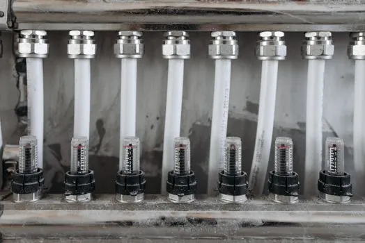
Thermal mass meters are available as insertion probes, inline flow bodies, or surface-mounted systems with a probe entering through a process connection [S4][S5]. The flow body must be compatible with the process gas, and the sensor assembly must match the line size and flow direction [S2]. FCI lists compressed air, nitrogen, biogas, digester gas, methane, and natural gas among named applications, with individual models covering 6–51 mm inline lines and insertion products for lines of 25 mm and above [S4].
Accuracy depends on installation quality as well as sensor design. Straight pipe lengths before and after the meter improve measurement quality, while flow-conditioning plates can address installations where those lengths are unavailable [S2]. For large lines, dual-element averaging is specified at 305 mm and above in relevant insertion models [S4].
Electronic selection is separate from process selection. Available outputs include 4–20 mA, pulse, HART, Foundation Fieldbus, PROFIBUS, and Modbus, while documented agency approvals include ATEX, IECEx, EAC, NEPSI, Inmetro, UKEX, and ECAS [S4]. These approvals support hazardous-area deployment, but they do not remove the need to match the certified gas group, temperature class, installation rules, and local site requirements.
Battery Power and Compactness Open Utility-Scale Opportunities
Thermal-mass gas metering offers excellent accuracy, compact construction, and ultra-low power consumption, with that last property identified as critical for battery-powered gas meters [S7]. These characteristics support demand from compact instrument makers and distributed gas-metering programs where device footprint and energy consumption constrain alternative technologies.
Low power does not remove the need for correct calibration and gas composition. Thermal meters require calibration factors for the measured gas, and the transmitter applies those factors before reporting mass flow [S2]. Gas properties, sensor geometry, installation orientation, and flow condition must therefore be handled as one engineering package rather than as independent purchasing choices.
The mass-spectrometer is a different instrument class, used to identify gas composition rather than measure bulk flow, but gas analysis may support calibration in complex mixtures. The practical purchasing sequence is to define the gas, pressure and temperature range, line size, minimum and maximum mass flow, installation geometry, power budget, output protocol, and hazardous-area classification before selecting the meter model.
Demand Signals Can Be Tracked Through Projects and Product Mix
The strongest demand indicators are application-specific rather than generic industrial expansion: compressed-air leak projects, natural-gas submetering, boiler and furnace fuel control, emissions-monitoring installations, wastewater aeration control, and battery-powered gas-meter programs [S3][S5][S7]. Each creates a defined need for direct mass measurement, compact packaging, or low-power operation.
Supplier breadth also offers a trackable signal. FCI lists more than 20 thermal mass flowmeter models, with line sizes from 6 mm to 305 mm, multiple insertion and inline configurations, analog and digital communications, and specialized options for pressure measurement or verification [S4]. More model breadth does not prove unit-market growth by itself, but a rising share of dual-element, pressure-compensated, or certified compact products would indicate movement toward larger lines and more demanding systems.
For buyers, the decisive test remains application fit. Confirm the gas and calibration basis, minimum and maximum flow, line size, available straight runs, pressure drop, output protocol, power source, and hazardous-area certification before ordering. For market tracking, monitor bid activity in compressed-air and natural-gas submetering, the mix of insertion versus inline products, and the appearance of more low-power devices designed around thermal mass sensing [S2][S4][S7].