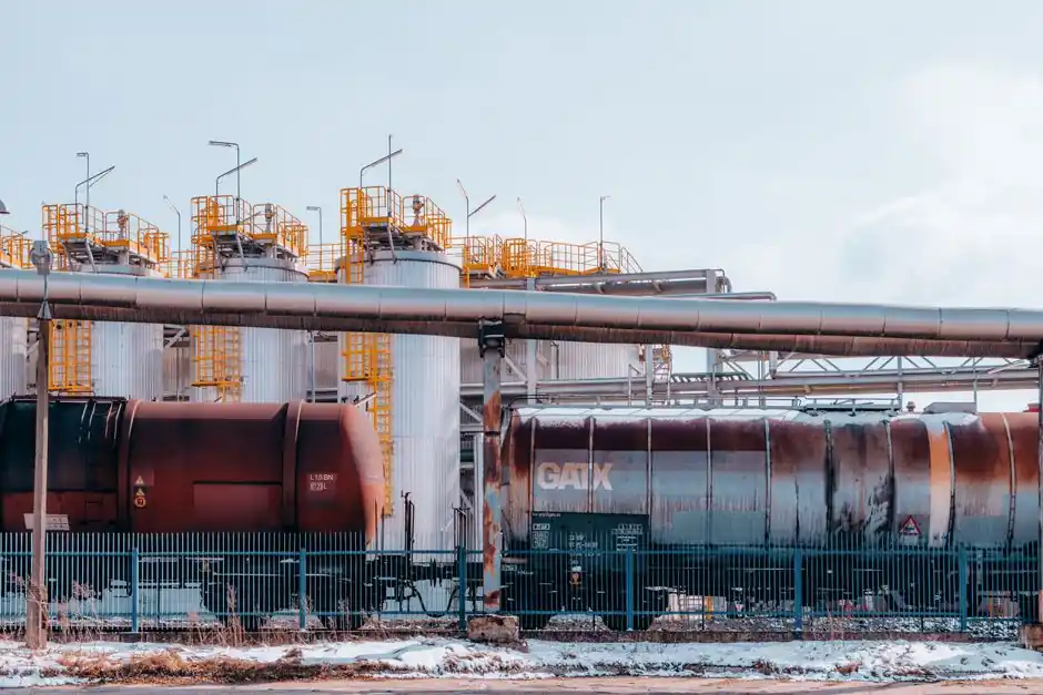
A chemical-plant toxic gas detection system (TGMS) is a life-safety layer built from point sensors, controllers, and annunciation that triggers shutdown, isolation, and evacuation, not just a measurement loop [S7]. The architecture is dictated by the gas inventory: each target species needs its own sensing chemistry because no single detector covers Cl2, NH3, H2S, CO, and VOCs at once [S2].
Design references converge on the same building blocks: a gas inventory, sensor technology matching, zone-based placement, redundant safety PLCs, and a maintenance loop driven by bump-test and span-calibration cycles. Standards touching the same architecture include ATEX 2014/34/EU and 99/92/EC for equipment and worker protection in explosive atmospheres, and the IEC/EN 60079 series for Ex-protection construction [S3].
Sensor Technology Selection by Target Gas
Sensor selection must follow the gas, not the other way around: electrochemical cells suit Cl2, CO, H2S, and NH3 at ppm levels, infrared (NDIR) sensors suit hydrocarbons and CO2, photoionization detectors (PID) cover low-ppm VOCs, and catalytic bead sensors remain the cheapest option for flammable-gas LEL measurement, but they degrade under silicone and phosphate poisoning [S3][S4]. An electrochemical cell cannot reliably detect silane or arsine, and a single technology deployment across a fab or plant creates documented blind spots [S2].
For hydrogen, the low explosion limit (4% vol in air) and buoyancy demand a different placement strategy and a catalytic bead or thermal conductivity sensor, while for chlorine, a heavier-than-air toxic gas with an IDLH of 10 ppm, an electrochemical sensor placed at low elevation is the workhorse [S3][S4]. Infrared sensors are described in supplier guidance as stable and less prone to contamination than catalytic types, a meaningful advantage in dusty or wet chemical-service environments [S4].
Placement Strategy: Density, Dispersion, and Fenceline
Placement rule of thumb from multiple OEM guides: lighter-than-air gases (H2, NH3 in warm releases, CH4) get ceiling or high-elevation detectors; heavier-than-air gases (Cl2, H2S, most refrigerants) get floor or low-elevation detectors near valves, flanges, pump seals, and storage tank vents [S4]. Dead legs, sumps, and poorly ventilated enclosures deserve dedicated points because stratification is common there.
For community-facing risk, fenceline monitoring uses a mixed-integer linear programming (MILP) optimization that weights sensor positions against CFD dispersion outputs, population density, and evacuation vulnerability; published case studies report that MILP-optimized arrays reduce exposed-area metrics relative to uniform spacing, especially when the surrounding community is unevenly distributed [S5]. The historical driver for this approach is the 1984 Bhopal MIC release (≈8,000 immediate casualties) and the May 2020 Visakhapatnam styrene release (12 fatalities) [S5].
Controller Architecture: Safety PLC, DCS, and SIL Ratings
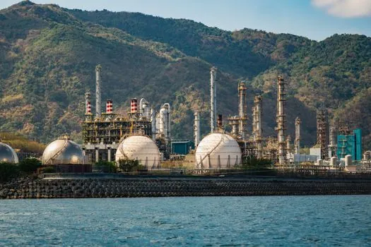
Field detectors are wired (or linked via wirelesshart/ISA100) to a dedicated safety PLC or a safety-integrated DCS layer, separate from the basic process control system (BPCS), to satisfy IEC 61511 / IEC 61508 SIL targets typically set at SIL 2 for toxic-gas alarms and SIL 3 for ESD-initiated isolation [S6][S7]. A typical GDS signal path runs: sensor → transmitter (4–20 mA, HART) → safety I/O → logic solver → annunciator + DCS interface + ESD/isolation valves + fire panel interface [S6].
Alarm architecture follows a two- or three-stage model: low alarm at a fraction of the occupational exposure limit (OEL) for early warning, high alarm at the OEL or IDLH for evacuation initiation, and a separate high-high trip that drives automatic isolation, regardless of operator acknowledgement [S2][S6]. Thresholds must be customized per gas, not lifted from a generic template, because the same ppm value can be sub-OEL for one species and orders of magnitude above OEL for another [S2].
Maintenance, Calibration, and Autonomous Correction
Electrochemical and MOS sensors drift with humidity, temperature, and prolonged exposure, so routine span calibration with certified test gas is treated as mandatory, not optional; Honeywell guidance explicitly frames skipped calibration as the root cause of false-negative leak events [S2]. A practical cadence from the same guidance is a 30–90 day bump test with full span calibration on a 6–12 month cycle, depending on sensor type and environmental stress.
For multi-sensor arrays, a 2025 systematic review in PMC concluded that machine-learning techniques (PCA, SVM, multivariate regression, and calibration transfer) can correct accuracy drift and improve selectivity against interference gases, reducing but not yet eliminating the need for manual calibration [S1]. The same review flagged open problems: drift dynamics under long exposure, multi-sensor time synchronization, and aligning ambient readings with lab-grade reference analyzers [S1].
Failure Modes and Selection Pitfalls
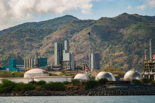
Common failure modes documented in industry guidance include: poisoning of catalytic beads by silicone or phosphate compounds, condensation on IR optics, electrolyte dry-out in electrochemical cells after 18–36 months, and cross-sensitivity where one species triggers a false reading on another species' sensor [S4]. Each failure mode is tied to a maintenance countermeasure, and the detector datasheet's poisoning list, cross-sensitivity table, and expected cell life are the three most-cited selection criteria [S4].
For a complete toxic gas detector specification, the project team should freeze the gas register, map each species to a sensing technology, run dispersion modelling for placement, and only then size the I/O and safety-PLC capacity. The general gas detection taxonomy and the chemical reagent reference both help non-specialists anchor terms like IDLH, TLV-TWA, and LEL to the same vocabulary across disciplines.
Standards, Compliance, and Documentation
European chemical-plant GDS designs reference ATEX 2014/34/EU (equipment) and 99/92/EC (worker protection in Ex zones), the IEC/EN 60079 series for Ex-equipment construction, and national occupational safety codes such as Italy's Legislative Decree 81/08 [S3]. In North America, the equivalent reference set is NEC Class I Division 1/2 wiring (or the IECEx zone model), NFPA 72 for annunciation, and ISA 84 / IEC 61511 for the safety lifecycle.
Documentation expected by auditors includes: a gas-register matrix, sensor coverage map, SIL target per loop, calibration and bump-test records, mean-time-between-false-alarm data, and a written management-of-change procedure for any sensor swap [S6][S7]. The architectural decisions that govern the rest, sensor-to-gas mapping, alarm-threshold setpoints, and SIL targets, are all decided in the first 10% of the project; the remaining 90% is execution and proof of maintenance discipline.
Two trackable signals for the next project review: (1) ML-assisted drift correction maturing past research pilots into vendor firmware on safety PLCs, which would shift calibration intervals from calendar-based to condition-based [S1]; (2) wider adoption of wireless detector networks (WirelessHART/ISA100) in Ex zone 1 areas, replacing the last hard-wired loops in brownfield plants [S6]. For broader context on how sensor-driven safety loops interact with rotating-equipment health programmes, see Belt and Chain Drive Monitoring for Conveyors: Sensor Stack, Failure Modes, Selection and on reliability workflow integration, see Bad Actor Analysis from CMMS Work Orders: A 2026 Reliability Engineering Reference.