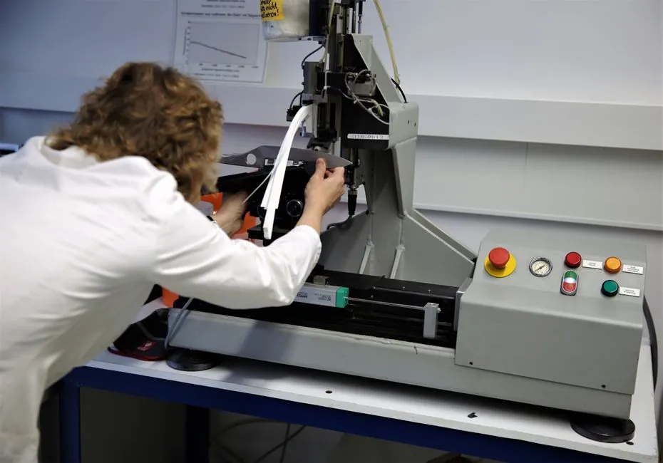
Ultrasonic longitudinal-wave velocity in ductile iron typically lands between 5,500 and 5,800 m/s, while gray cast iron with flake graphite reads closer to 4,500 m/s; the ~1,000 m/s gap is the physical basis for using sound speed to verify graphite nodularity [S1][S7].
The test is a through-transmission pitch-catch measurement across two parallel surfaces of the casting, using three time-of-flight values (TOF1, TOF2, TOF3) from which both velocity and wall thickness are solved algorithmically, with no prior thickness input needed [S2]. Production lines use this principle to screen 100% of parts, sorting accept/reject against preset velocity limits that have been calibrated against metallographic reference castings [S2].
What "Nodularity" Means and Why Sound Velocity Tracks It
Nodularity is the percentage of graphite particles in a cast iron matrix that exist as near-spherical nodules rather than flakes; ductile (nodular) iron is qualified to ASTM A536 grade 60-40-18 / 65-45-12 / 80-55-06 families, and a minimum 80% nodule count is the typical acceptance threshold for safety-critical parts [S3].
Graphite morphology changes the elastic stiffness of the iron: rounded nodules scatter and attenuate ultrasonic waves far less than the sharp flake tips that act as stress concentrators in gray iron, so the longitudinal wave speed shifts measurably with the nodule-to-flake ratio [S7][S8]. Because velocity is a bulk property averaged over the sound path, a single through-transmission reading integrates thousands of graphite particles, which is why a properly calibrated fixture can grade an entire brake caliper or hub in well under a second [S2].
Orłowicz et al. (2010) further established that longitudinal-wave velocity measurement on liquid and just-solidified ductile iron can diagnose melt quality before pouring, extending the same velocity-nodularity correlation upstream of the foundry floor [S5].
Equipment: Transducers, Fixtures, and Industrial Instruments
Standard 1–5 MHz contact or immersion longitudinal transducers are the workhorse probe; MAC's Echomac® VM and the Echomac® Velocity Measurement module are purpose-built industrial instruments that read velocity directly on cast automotive components in production cells [S4].
Evident (formerly Olympus IMS) industrial systems integrate the same pitch-catch arrangement with three-TOF thickness/velocity calculation, a GO/NOGO operator interface, and digital I/O to a PLC for automatic accept/reject sorting, and they are typically mounted in an immersion tank with mechanical pick-and-place or robotic part loading [S2].
For research and higher-temperature melt-quality work, EMAT (electromagnetic acoustic transducer) shear-wave velocity is an alternative: US patent 5,714,688 covers calculating V<sub>SHEAR</sub> from an EMAT-equipped test and converting it to a percent nodularity reading, useful where couplant-free or hot-surface measurement is needed [S6].
Method: Calibration, Limits, and Reference Standards
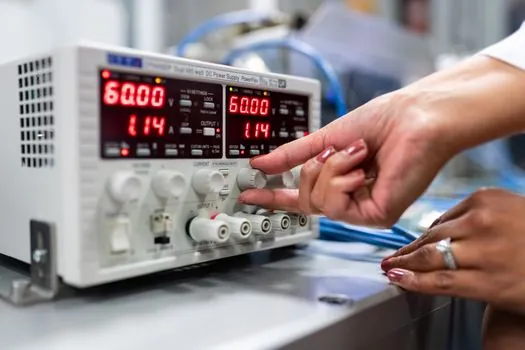
Calibration is the make-or-break step: the system is normalized against reference castings produced from the same geometry and heat as production parts, and the GO/NOGO velocity limits are tightened until they agree with destructive metallographic nodularity counts on a sampled lot [S2].
Part fixturing is held to tight tolerances, because the three-TOF algorithm assumes the part sits at a repeatable position relative to the probes; any shift in standoff or angle changes the apparent velocity and can cause false rejects [S2]. For a process line, accepted parts proceed while rejected parts are typically re-tested once to rule out a positioning error before being scrapped or diverted to a lower-grade heat [S2].
The method assumes a consistent matrix: ferrite vs pearlite ratio, alloy content, and section thickness all shift the absolute velocity number, so velocity limits are heat- and part-specific, not a single universal value across a foundry [S1][S3].
Velocity Test vs Metallographic Nodularity Count: Decision Comparison
Metallography is the traditional reference: a sample is sectioned, polished, and the nodule count is read by a metallurgist at 100x, giving a direct percent nodularity on that one coupon; the test is destructive, slow (often 30+ minutes per sample), and qualified by human interpretation [S2][S3].
Ultrasonic velocity is non-destructive, sub-second per part, and run on 100% of production, but it returns a velocity number that must be correlated back to percent nodularity through a calibration curve built from metallographic data on the same part [S2]. In practice, foundries run both: velocity screens every casting on line, and metallography is retained for periodic calibration, dispute resolution, and new-part bring-up [S1][S2].
The table below summarizes the decision criteria for selecting between (or combining) the two methods on a ductile iron production line.
Selection Criteria: When Velocity Is the Right Tool, and When It Is Not

Ultrasonic velocity testing is the right primary inspection for high-volume safety-critical ductile iron parts (brake components, suspension knuckles, hub knuckles, certain pipe fittings) where 100% coverage matters and the geometry gives two clean parallel surfaces for through-transmission [S2][S4].
It is the wrong primary tool for low-volume or one-off castings, parts with complex geometry and no parallel surfaces, applications where absolute percent nodularity (not a relative accept/reject band) must be reported to a customer, and any case where matrix composition varies part-to-part, because the velocity-to-nodularity correlation breaks down [S1][S3].
Foundries also need to budget for reference standards, fixture machining, and a metallographic tie-in during commissioning; treating the velocity tester as a "plug and play" black box is the most common cause of false-pass failures in the field [S2].
Use Cases on Real Production Lines
Automotive ductile iron brake calipers, steering knuckles, and differential carriers are the canonical high-volume use case, where pick-and-place or robotic loaders feed parts into immersion fixtures at cycle times well under 5 seconds, with accepted parts continuing to machining and rejected parts sorted automatically by digital I/O [S2].
Beyond finished castings, longitudinal-velocity measurement on tapped samples from the pouring ladle or on the just-poured melt (per Orłowicz's work) lets the foundry decide whether to adjust magnesium treatment before a bad heat reaches the mold, raising first-pass yield on the casting line [S5].
For pipe and pressure-retaining components where the casting is large and section thickness varies, the same pitch-catch principle is applied across shorter paths and the velocity reading is used as a screening tool, with full-section ultrasonic C-scan or radiography reserved for the parts that pass the velocity gate [S2].
Limitations, Failure Modes, and Standards Anchors
The dominant failure mode is calibration drift: as matrix chemistry or pearlite fraction shifts heat-to-heat, the velocity-to-nodularity curve slides and previously accepted parts can be over- or under-rejected until the reference standards are re-baselined [S1][S2].
Other failure modes include poor couplant or standoff variation in immersion cells, porosity that biases the time-of-flight reading, and laminar defects near the surface that distort the third echo (TOF3) used for thickness/velocity calculation; pulse-echo probes can be added in the same fixture to flag these and prevent a bad casting from passing the velocity gate [S2].
Standards anchoring: ASTM A536 defines the ductile iron grade family, and the velocity method is widely reported in the foundry NDT literature as a complement to, not a replacement for, metallographic nodularity counts on calibrated samples [S3][S7].
What the Sound-Speed Number Looks Like in Practice
For a typical pearlitic-ferritic ductile iron automotive part, expected longitudinal velocity falls in the 5,500–5,800 m/s band, with high-nodularity (greater than 90%) material sitting near the top of that range and mixed-nodularity (60–80%) material trending lower [S1][S7].
Foundries typically set a lower accept limit 100–200 m/s below the calibrated "good" reference to allow for section-size and matrix variation, then re-tighten once they have 30–50 production heats of correlation data against metallography [S1][S2]. A 4,500 m/s reading is a strong flag that the casting has reverted toward gray-iron flake structure and should be metallographically confirmed before any downstream use [S7].
For broader background on the metal family itself, see the cast iron encyclopedia entry; for the underlying ultrasonic test method, the ultrasonic flaw detector and ultrasonic sensor pages cover the general principle; and for thickness/thin-wall measurement on castings and pipe, the ultrasonic thickness gauge and ultrasonic level meter pages cover adjacent industrial uses. Foundries pairing this with ultra-high carbon steel heat treatment or squeeze cast vs gravity cast A356 process control will recognize the same logic of using a bulk physical property to grade microstructure at line speed.
Track the following signals over the next reporting cycle: new ASTM A536 revision or A395 line calls for ultrasonic verification; Evident or MAC product updates adding inline EMAT or phased-array nodularity options; and any SAE/AFS foundry-NDT working-group publication formalizing velocity-limit-setting practice.