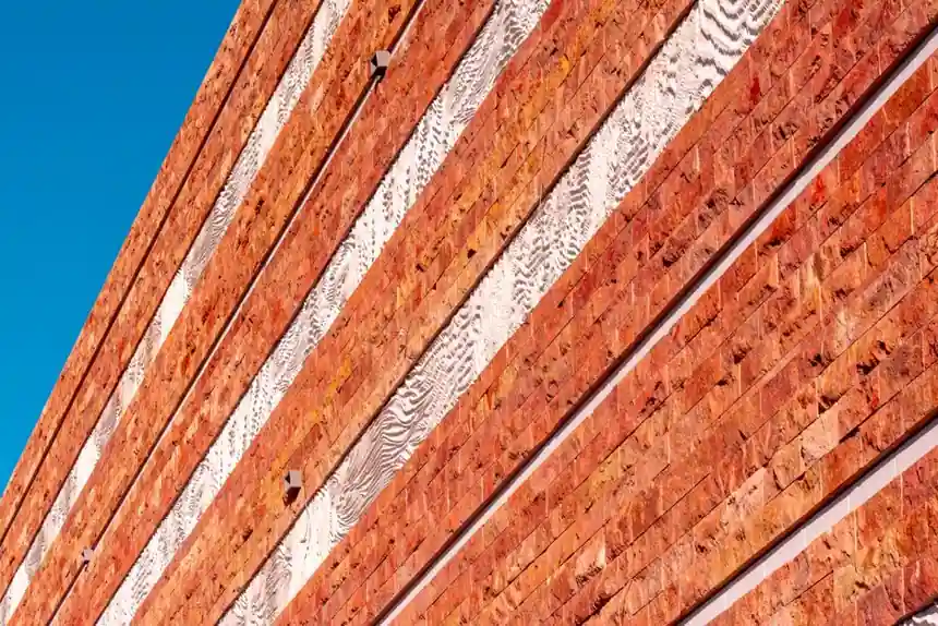
Undercut anchors offer concealed form-fit connections without panel-edge slots, while kerf anchors support panels through edge recesses and pins provide discrete drilled connections.
For exterior stone cladding, the controlling criteria are stone strength, edge distance, installation access, movement accommodation, corrosion resistance, and project-specific pull-out performance.
Choose by Connection Geometry and Load Path
Undercut anchors create a mechanical interlock inside a back-drilled cavity, transferring load through the panel thickness rather than through a weakened edge [S2][S5]. A representative system comprises a sleeve, threaded pin, nut, and locking ratchets; the KEIL KH AA catalogue identifies stainless steel A4 components, M6 and M8 examples, and a 1–6 Nm torque wrench accessory [S5].
Kerf anchors engage a continuous slot or a disc-shaped recess machined into the panel edge. Published design guidance states that stone anchorage systems must accommodate thermal expansion, structural deflection, seismic loads, and wind pressures without inducing excessive stress in the relatively brittle stone material [S1]. Pin anchors use cylindrical pins installed in drilled holes, creating point connections rather than distributing load along a kerf line [S3].
For panel geometry, undercut anchors support panels with no edge modification, including 8–12 mm porcelain when edge distance is adequate [S2]. The fixing guide evaluates undercut anchors, kerf-slot agraffe brackets, and dowel-pin systems as mechanical stone-cladding fixing methods [S4]. These are project-selection ranges, not universal product limits.
Compare Capacity, Edge Risk, and Installation
Concrete capacity alone does not establish a safe stone anchorage: the design value remains governed by the interaction of stone breakout, anchor mechanics, and minimum edge distance. Project samples should therefore undergo pull-out testing rather than deriving acceptance from bolt datasheets alone [S2].
The comparison below separates the main selection variables:
The KEIL undercut anchor catalog lists M6 and M8 anchor variants with associated panel thicknesses, insertion depths, clamping thicknesses, and nominal lengths [S5]. The comparison source describes undercut anchors as distributing stress inside the panel and kerf systems as concentrating stress at the panel edge [S2].
The fixing guide states that mechanical dry-hanging systems transfer gravity and wind loads from the stone panel directly to the building structure through engineered connections [S4]. These figures are not interchangeable with project allowables: stone variability, cavity geometry, edge distance, installation torque, corrosion class, and the selected approval must be evaluated separately.
Match the Anchor to Stone Type and Panel Size
Undercut anchorage is the stronger functional choice where the panel edge is inaccessible, the visual joint must conceal the fixing, or the panel is too thin to accept a reliable kerf. The internal connection avoids the kerf-induced stress riser, and the KEIL system permits a small rotational movement after assembly rather than leaving the anchor under expansion pressure [S2][S5].
Kerf anchors remain appropriate for thick stone, controlled shop fabrication, economical projects, and buildings where edge access is available. Their advantage is direct support from the edge and a broad range of blade, disc, split-tail, and spring-loaded configurations [S1]. The limitation is concentrated edge demand: a 1/2-inch kerf is one-half of a 1-inch panel thickness, so the remaining edge section requires deliberate engineering.
Pin and dowel systems suit thicker, heavy stone units where holes can be accurately drilled and brackets can maintain alignment. Most stone projects are unique and require custom anchors [S3]. Anchored dimensional stone is treated as a special system requiring engineering rather than being covered as a routine masonry detail [S3].
For natural-stone specification, the building stone selection must precede anchor selection. The anchor-design source states that stone remains one of the strongest and most durable building products [S3]. Pull-out validation on representative project material is the decisive evidence.
Set Geometry, Movement, and Structural Checks
A practical undercut layout requires the undercut diameter, insertion depth, sleeve length, pin length, and bracket thickness to match one approved system. KEIL lists drill diameter D1 of 7 mm, undercut diameter D2 of 9 mm, a 9 mm spanner size, and a 3 mm clamping thickness for its KH AA 9/12 examples [S5].
Stone cladding must accommodate thermal expansion, structural deflection, wind, and seismic movement without overstressing brittle panels [S1]. Kerf and pin connections may provide directional adjustment through brackets or slots, while the undercut anchor remains a discrete point connection and requires deliberate movement accommodation at the supporting bracket.
The broader architectural hardware assembly must be designed as a system, including anchors, brackets, rails, fasteners, and restraints. The fixing guide states that mechanical stone-cladding system specifications require evaluation of wind loads, seismic movements, thermal expansion, stone flexural capacity, and corrosion resistance [S4].
Support conditions also control the check. The backup structure may be concrete, concrete masonry, wood, or metal studs; existing concrete and CMU backup walls may require pull-out testing to demonstrate capacity [S3]. Anchor strength cannot compensate for a deficient substrate connection.
Corrosion, Fabrication, and Quality Control
Most mechanical stone anchors are manufactured from Type 304 stainless steel, while Type 316 is selected for marine exposure [S3]. The KEIL undercut system uses A4 stainless steel [S5]. Coastal or chloride-exposed environments require project-specific consideration of fastener grade, isolation between dissimilar metals, drainage, and replacement access rather than a generic 304 assumption.
Kerf fabrication demands controlled saw or wire cutting, a clean and accurately dimensioned slot, and non-staining silicone or EPDM inserts where specified to accommodate movement and avoid hard metal-to-stone contact [S4]. Undercut fabrication demands specialist drilling equipment: a conical or stepped cavity cannot be produced accurately with an ordinary straight drill. Both methods require templates, hole or slot location control, and inspection before the stone reaches the façade.
For kerf anchors containing bends, anchor-hole fabrication matters. A cited fabrication rule places the hole at least (2 × anchor thickness) + (0.5 × anchor thickness) from the inside bend dimension; for 1/8-inch anchor stock, that equals 0.3125 inch, or 5/16 inch [S3]. The rule is for the described anchor fabrication condition, not a universal requirement for every kerf or dowel arrangement.
Define Acceptance Tests and Approval Documents
Acceptance should include drawings for panel numbering, anchor type, drill or kerf dimensions, edge distance, support-bracket type, and installation torque. KEIL specifies controlled screw insertion so the sleeve expands to its intended geometry, with locking ratchets securing the screw to the bracket [S5]. Its instructions require matching sleeve and screw lengths to the desired insertion depth and bracket, and use of a 1–6 Nm torque wrench [S5].
Project pull-out tests should use representative stone, including the panel finish and the intended drilled cavity. For comparison, the KEIL catalogue identifies external monitoring and an ETA, while instruction compliance must be checked against the applicable approval and assembly instructions [S5]. Standards cited for façade design include DIN 18516-3, ASTM C1242, and BS 8298 [S4].
Do not transfer a published M6 capacity of 14 kN or M8 capacity of 24 kN directly into a project schedule. Record the lesser controlling condition: anchor mechanical resistance, stone cone breakout, local flexural strength, edge distance, movement, corrosion, and backup-substrate capacity [S2]. This avoids selecting the stronger-looking anchor while under-designing the stone.
For the next procurement action, freeze the stone panel thicknesses and backup framing, then issue undercut, kerf, and pin alternatives with the same project-specific stone and wind data so fabrication tolerance, capacity, and installed cost can be compared directly.