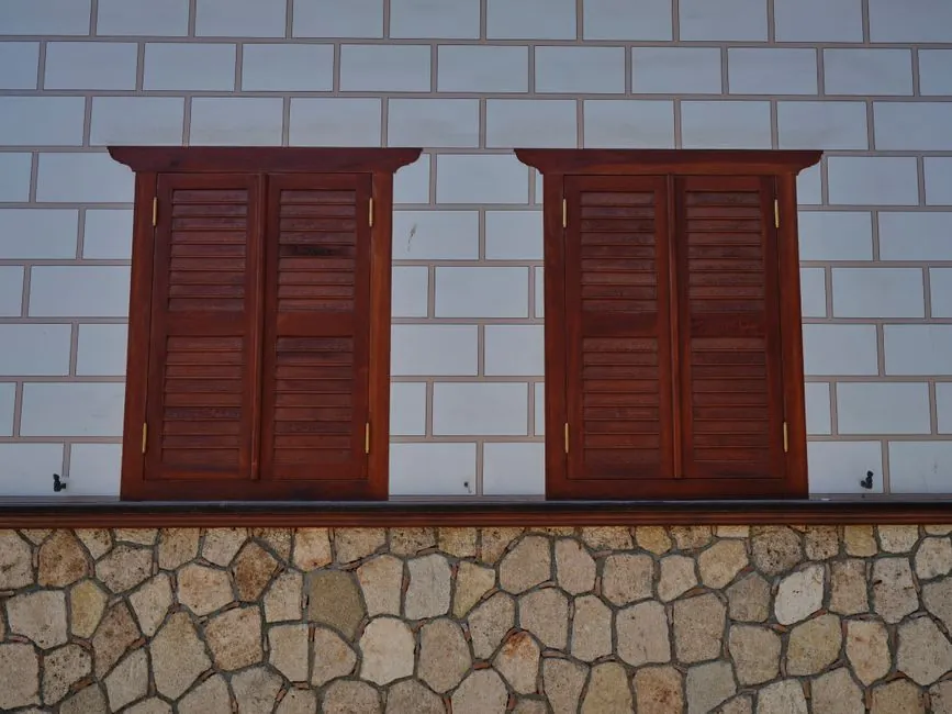
A tall stone panel should use independently anchored supports designed to accommodate vertical loads from stone-unit self-weight and lateral loads [S3].
In an independently supported veneer system, each stone panel is relieved and restrained by mechanical anchorage attached to the backup wall substrate [S3].
Why a Tall Stone Panel Needs Its Own Support Design
The panel and anchorage system must carry three primary actions: vertical dead load from the stone, lateral load from wind, and lateral load from seismic movement [S2][S3]. Thermal movement also enters the design because stone, metal framing and the backing structure do not deform identically [S4].
Panel height increases the number of anchors and changes the load path. The distance between anchor points, or support span, affects the stress generated in the panel and its connections [S2]. A tall panel therefore cannot be specified from stone thickness alone: the engineer must evaluate panel flexure, anchor spacing, support stiffness, edge conditions and the backing structure together [S1][S2].
The system scope extends beyond the visible stone. An engineered assembly must address anchorage, joint design, flashing, fabrication, field measurement, supervision, and cleaning and maintenance [S1]. This makes the support system a complete architectural and structural interface, not a decorative bracket selected from a catalog.
Select Independent Support Over Stacked Veneer
An independently supported veneer restrains and relieves each stone panel with mechanical anchorage attached to the building structure, masonry backup, stud framing or miscellaneous steel [S3]. The vertical and lateral loads are transferred directly to that substrate, while joints remain free of shims, mortar or other rigid material capable of transferring load between adjacent stone units [S3].
A stacked veneer with relieving supports uses lateral ties or straps for wind and seismic restraint, while continuous angles or clips carry the accumulated vertical weight above each relief point [S3]. Relief supports are normally provided over openings and at each story height, with a maximum vertical spacing of 20 feet, and the stack below a support transfers weight through load-bearing shims or mortar [S3].
Anchor Spacing and Panel Geometry Drive Stress
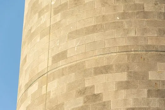
Increasing the distance between anchor points raises the span and changes the stress carried by the stone panel and connections [S2]. Anchor spacing must therefore reflect the panel width, height, thickness, material, finish, edge support and calculated load case rather than a rule based on panel height alone [S1][S2].
Natural stone requires a specific strength assessment because geological variation affects panel behavior. The cited reference includes sections on geologic categories of stone and the trade classification of granite, marble, and sandstone [S1]. A tall panel design should identify the stone variety and establish the physical properties used for flexural and anchorage checks [S1].
The panel proportions also affect support demand. A narrow, tall panel can combine substantial self-weight with limited bending stiffness, while a wider panel may require more anchors to maintain edge support. The engineer should check load combinations including gravity, wind and seismic action, then verify anchor strength, pull-out, pry-out, bending and connection capacity using the selected substrate and installation conditions [S1][S3].
Build the Joints for Movement, Not Load Transfer
The joint must remain capable of compressing and extending without transferring structural load from one stone unit to another, which is why rigid mortar or shims are excluded from an independently supported, relieved arrangement [S3].
Sealants and gaskets at metal-to-wall interfaces must accommodate ultraviolet exposure, temperature fluctuation, moisture, and differential movement of stone and metal framing [S4]. Silicone and polyurethane are cited as common high-performance sealant materials, while drainage cavities behind panels can remove incidental water that bypasses the primary seal [S4].
Halfen installation guidance specifies at least a 3/32-inch gap between the top edge of a panel and the underside of the second support row [S7]. That clearance is a component adjustment instruction, not permission to reduce the 3/8-inch exterior veneer joint. Both requirements serve different functions: one separates adjacent rows to prevent unintended contact, while the other accommodates movement around the visible stone joint [S3][S7].
Specify Water Management as Part of the Support System
Stone panels are not normally the primary weather barrier; waterproofing and moisture-management components commonly sit behind the panels, at attachment points and at interfaces with the building structure [S4]. Continuous sealants or gaskets around framing and clips reduce water entry, while flashing at corners, openings and cladding transitions directs water away from vulnerable connections [S4].
Three construction layers must remain coordinated: the substrate, the metal support and anchorage system, and the stone panel with its joints. Flashings made from stainless steel or aluminum are used at critical transitions, and drainage channels or compartments may be installed behind the panels [S4]. A building stone specification that stops at slab dimensions and finish omits the components most likely to control long-term facade performance.
For an engineered assembly, the submittal should identify the backing-wall construction, attachment type, anchor spacing, panel dimensions, stone properties, joint size, sealant, flashing, drainage path and inspection hold points. The design team also needs to define how a panel is removed without transferring load into adjacent stone, because repair work is part of the facade system rather than a separate trade decision [S1].
Match the Support Strategy to Project Conditions
Mechanical restraint is appropriate when a tall stone panel must transfer gravity, wind and seismic loads directly to a structural or engineered backing wall [S3]. A stacked system can reduce attachment demand at each panel, but it introduces continuous relief angles or clips, story-based support lines and load-bearing joints that must be detailed for cumulative weight [S3].
Aluminum backing systems can provide support and durability by relying on metal strength rather than relying on the stone for structural continuity [S6]. That approach is not interchangeable with every clip, pin, undercut or kerf anchor. The comparison between undercut versus kerf-and-pin anchors matters because concealed-profile systems have different engagement geometry and fabrication requirements from pin-supported panels.
This support strategy is for engineered exterior cladding where a qualified professional can verify the structure, stone properties, connections and installation tolerances. It is not a generic method for a low knee wall, an isolated decorative panel or an unverified backing assembly. A porch example involving a 4-by-6-foot enclosure, a 22-inch gap, a 19-inch-wide wall, a height of 34–40 inches and an estimated 500-pound load per side illustrates why dimensions, footing and substrate conditions must be resolved rather than copied from a generic facade detail [S5].
Quality Control Depends on Traceable Installation Data
Recommended practices divide stone construction into 18 subjects, including installation methods, recommended test methods, anchoring, safety factors, jointing, flashing, fabrication, shipping, storage, survey, field measurements, supervision and maintenance [S1]. That sequence establishes the support design as the starting point, not the final deliverable, because fabrication and installation tolerances determine whether the designed connection behaves as calculated.
Field verification should confirm panel dimensions, support locations, anchor geometry, substrate, joint clearances and drainage continuity before panels are permanently closed. For natural stone, the selection, finish and anchorage decisions must be coordinated with the quarry and fabricator, because panels can contain geological flaws or voids that alter the assumed behavior [S1].
Trackable project signals are specific and inspectable: approved shop drawings showing the support grid and load path, recorded anchor installation, documented joint and panel tolerances, and inspection records confirming flashing and drainage continuity. Any change to panel thickness, anchor spacing, substrate or support type should trigger a design review before fabrication proceeds [S1][S2][S3].