
Correct VFD sizing starts with motor Full Load Amps, not nameplate horsepower, because a drive's continuous current rating must equal or exceed motor FLA times service factor [S1]. Add an overload factor of 1.5 for constant-torque loads, and 1.1-1.2 for variable-torque loads, before picking a frame [S1][S3].
Voltage class is non-negotiable: a 460-480V facility requires a 480V class drive, and a 150% for 60s overload rating covers conveyors, positive-displacement pumps, and extruders running at constant torque [S1][S6]. Treat the HP/kW number as a sanity check, not the sizing input, because two motors with the same kW can differ by 30% or more in FLA.
Match the Drive to FLA, Then Verify the Nameplate
The drive's continuous output current must be greater than or equal to motor FLA times service factor, with a heavy-duty rating defined as 150% of rated current for 60 seconds for constant-torque applications like conveyors and extruders [S1][S6]. A normal-duty or variable-torque rating, typically 110-120% for 60s, suits centrifugal fans and pumps where load drops with speed squared [S6].
Gather nameplate data first: voltage, FLA, HP/kW, service factor, base frequency, and insulation class, then ignore any existing drive size and size fresh [S1]. Dual CT/VT rated VFDs are worth the small premium on mixed-duty lines because one hardware SKU covers both pump and conveyor cells, simplifying spares and reducing the part-number count on the BOM. Voltage class must match facility supply exactly, so a 208/230V or 460/480V three-phase line locks the drive family before any current calculation.
Insulation, dv/dt, and Reflected-Wave Limits
Inverter-duty motors qualify to NEMA MG-1 Part 31 (North America) or IEC 60034-18-41 (international), withstanding PWM voltage spikes that can reach roughly 1,600 V peak on a 480 V system with rise times measured in tenths of a microsecond [S4]. Without that insulation system, standard motors suffer turn-to-turn and phase-to-ground failures once cable length and switching frequency push dv/dt above the winding's rated limit.
For long motor leads, typically above 15-30 m on 480V IGBT drives, a dv/dt filter or sine-wave filter is the conservative path, paired with reinforced winding insulation and an insulation class of F (155°C) or H (180°C) [S3][S8]. The YVFE5 series from one Chinese OEM, for instance, ships with Class F insulation (optional Class H), IP55 protection, and a frequency conversion range up to 5-100 Hz, which is the envelope most CT/VT applications actually need [S3]. When in doubt, an inverter-duty nameplate is cheaper than a rewind.
Low-Speed Cooling: Why TEFC Motors Fail on VFDs
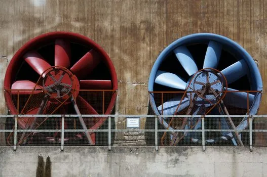
A TEFC motor's shaft-mounted fan slows with RPM, so a constant-torque load at 10-20 Hz will overheat the winding even though current is well within nameplate [S8]. Independent forced cooling, coded IC416 in IEC nomenclature, holds frame temperature flat across the full 5-100 Hz range and is the standard fix for low-speed CT duty [S3].
Vector-duty motors with auxiliary blowers can support 1000:1 constant-torque turndown for precision winding and tension control [S8]. For HVAC and pump stations, where load drops with speed, self-ventilated TEFC is usually fine down to about 20 Hz, below which either a TEBC (totally enclosed blower-cooled) motor or an external blower kit is the cost-effective upgrade. See the VFD-Duty Motor encyclopedia entry for the insulation-class and IC-code mapping reference.
Bearing Currents and Shaft Voltage
PWM common-mode voltage couples capacitively onto the rotor and discharges through the bearings, which is why large frames above roughly 100 kW typically need a grounding ring at the drive end and an insulated bearing at the non-drive end [S4]. An insulated bearing alone does not eliminate shaft voltage; it only blocks one current path, and the discharge will reroute through the driven load's bearings unless the system is also bonded symmetrically.
For frames under 30 kW, bearing-current mitigation is rarely specified, but once you cross 75-100 kW on 480V IGBT drives, treat shaft grounding as standard scope. Skipping it on a large press or extruder drive is the kind of decision that surfaces as a six-figure bearing-failure audit eighteen months after commissioning.
Sizing Criteria Compared: CT vs VT vs Vector-Duty
Four realistic motor options line up against four decision criteria for typical industrial cells: [S3]
1. Standard induction + standard VFD: lowest cost (baseline 1.0x), restricted to 60 Hz sinusoidal operation, no low-speed CT, no PWM insulation; suitable only for bypassed or rarely cycled loads. 2. Standard induction + VFD with dv/dt filter: cost about 1.2-1.4x baseline, full speed range, marginal low-speed CT for short cycles; suits fans and most pumps on 480V with leads under 15 m. 3. Inverter-duty motor (NEMA MG-1 Part 31 / IEC 60034-18-41) + matched VFD: cost about 1.5-2.0x baseline, full 5-100 Hz CT with IC416 cooling, PWM-rated insulation, 150% / 60s overload verified; this is the right answer for conveyors, extruders, hoists. 4. Vector-duty motor + vector VFD with encoder feedback: cost about 2.5-3.0x baseline, 1000:1 CT turndown, sub-1% speed regulation, dynamic braking; required for precision winding, synchronized press lines, and high-response tension control [S3][S4][S8].
Pick option 3 by default for any CT application above 5 kW, and reserve option 4 for true closed-loop positioning. Options 1 and 2 are the right call when a VFD is being added to an existing fleet and a derated service factor is acceptable, but they should be a procurement decision, not a default. For a deep dive on automotive transfer lines where the CT budget is tight, see the best VFD-duty motor for automotive lines spec map.
Environment, Altitude, and Derating
Derate the drive for ambient temperature above 40°C, altitude above 1,000 m, and carrier frequency above the manufacturer's default, because each factor cuts the effective continuous current rating [S1].
Cabinet heat dissipation matters because VFD losses run 2-5% of throughput, so a 100 kW drive dumps 2-5 kW into the enclosure [S1]. Zero-stack mounting helps density, but the cooling math still has to balance. For hazardous-area installations where the drive or motor sits inside an Ex zone, the explosion-proof motor spec map lays out the ATEX/IECEx cross-classification work that has to happen in parallel with the VFD selection.
Where This Selection Goes Wrong

The single most common error is sizing by HP and ignoring FLA, which leaves no headroom for service factor and overload, and trips the drive on the first conveyor stall [S1]. The second is mismatching voltage class, 230V motor on a 480V drive, which is field-fatal at energization. The third is forgetting that a standard NEMA Premium motor will run on a VFD most of the time, but its insulation was never qualified to Part 31, and it will fail early when cable length, switching frequency, and low-speed duty stack up [S4].
A standard induction motor is the wrong pick when the application runs constant torque below 30 Hz for more than a few minutes per cycle, or when cable length exceeds roughly 15 m on 480V IGBT drives without a filter. Inverter-duty is mandatory for new CT builds; standard is acceptable for retrofit VT-only fans where the existing motor is sound and the VFD is added for energy savings with a documented load profile. For the broader motor spec context across the IEC duty and IP families, the VFD encyclopedia page is the natural starting reference, and the medium-voltage VFD entry covers the >1,000V class where application-engineer involvement is the rule rather than the exception.
Trackable signals for 2026: NEMA MG-1 Part 31 and IEC 60034-18-41 remain the two standards to cite on the nameplate, and the next real procurement question is whether IE5 ultra-premium efficiency [S3] has dropped enough in price to become the default for CT cells, or whether IE4 inverter-duty still wins on $/kW for retrofit work.