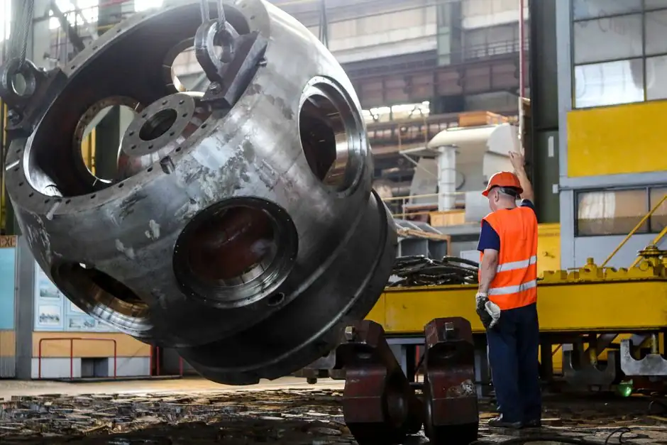
An explosion-proof motor is a containment-class machine, not a sealed box, and the difference matters when the wrong unit sits on a Class I Division 1 pump pad. Under IEC 60079-1, a flameproof (Ex d) enclosure is engineered to survive an internal deflagration and cool escaping gases below the auto-ignition temperature of the surrounding atmosphere through precision-machined flamepaths [S2][S5].
Selection is driven by four independent gates: the hazardous-area classification, the gas or dust group, the temperature code, and the driven-equipment duty (pump, compressor, fan, mixer, conveyor). Inventory programs in the field commonly stock ratings up to 2,500 HP and cover NEMA frame sizes that match both new installations and direct replacements for failed units [S1].
Define the Hazard Before Touching a Catalog
The first gate is the area classification, and it overrides every other decision. Under NEC Articles 500-506, a Class I Division 1 location is one where ignitable concentrations of flammable gases or vapors may exist under normal operation, which is where the most robust containment designs are required; Class I Division 2 limits the hazard to abnormal conditions and can accept lighter-duty enclosures [S1][S2]. The IEC/ATEX equivalent, Zone 1 versus Zone 2, follows the same logic and is what European and Middle Eastern specifications call out under ATEX Directive 2014/34/EU [S4][S5].
Gas group sits on top of the zone. NEC recognises Groups A (acetylene), B (hydrogen), C (ethylene), and D (propane), while IEC groups them as IIA, IIB, and IIC; a motor certified for Group D is not automatically approved for hydrogen service, and any cross-walk between the two systems has to be done gas-by-gas [S2]. Temperature code (T1 through T6) caps the motor surface temperature below the auto-ignition temperature of the specific gas present, and the most common misspec in the field is overlooking the T-code for dust atmospheres, where IEC 60079-31 sets a separate surface-temperature ceiling [S4][S5].
Containment vs. Prevention: Why Ex d and Ex i Are Not Interchangeable
Explosion-proof (Ex d / XP) and intrinsically safe (Ex i) protect against ignition with opposite philosophies, and they are not field-swappable [S2][S5]. Explosion-proof designs assume an internal ignition will occur and rely on a heavy enclosure (cast iron, cast aluminum, or stainless steel with 6-12 mm walls) plus machined flamepaths to contain and cool the combustion products; intrinsically safe designs instead cap the available voltage, current, and stored energy below ignition thresholds, even under simultaneous component faults [S3][S4][S5].
That physical difference dictates where each concept fits. Motors, lighting, and switchgear are high-power loads that cannot be energy-limited, so they fall on the Ex d / XP side; instrumentation, flow meters, pressure transmitters, and tank-gauging circuits sit on the intrinsically safe side because they operate with milliwatts and a Zener barrier or galvanic isolator can hold them below ignition energy [S3][S4][S5]. A full process skid will typically mix both: an explosion-proof motor on the pump shaft, an explosion-proof junction box feeding it, and intrinsically safe signal wiring for the transmitters that read its suction and discharge pressure.
Flamepath Engineering: the Numbers That Decide Pass or Fail
Inside a flameproof enclosure, the flamepath is the engineering control, and IEC 60079-1 sets the dimensional envelope. Typical maximum gap values land at 0.4-0.5 mm on axial joints and 0.2-0.35 mm on radial joints, with a minimum flamepath length of 8-25 mm depending on gas group and enclosure volume; the joint surface finish is held to Ra ≤ 6.3 µm, and the enclosure itself has to survive a reference pressure of 3.5-12 bar(g) during the type test [S2].
For Group IIC (hydrogen and acetylene, the most demanding family), the maximum experimental safe gap shrinks, the flamepath length grows, and wall thickness on a 10-litre enclosure can reach 8-10 mm; for Group IIA (propane) the same enclosure can be lighter and the gap can open up [S5]. Cable entries are part of the same system: only certified Ex d cable glands with proper stopping boxes count, and in North American conduit installations, NEC 501.15 requires the seal fitting to be poured within 450 mm of the enclosure [S5]. Damaged threads, scratched flange faces, or substitute gaskets void the certification regardless of how the motor performed on the test bench [S3].
Comparison Table: Ex d / XP vs. Ex e vs. Ex nA vs. Ex i for Motors
Three motor-side protection concepts compete in the same hazardous-area envelope, plus the intrinsically safe option that never applies to motors but always shows up in the same spec. Flameproof (Ex d, "explosion-proof" in US NEC/UL 674 language) contains an internal explosion, suits Zone 1 / Class I Division 1, gas groups IIA-IIC, and high-power loads from fractional kW up to multi-MW [S2][S5]. Increased safety (Ex e) keeps the internal atmosphere out of the explosive range by tighter creepage, stronger insulation, and locked-rotor protection, and is usually paired with Ex d terminal boxes; it fits Zone 1 auxiliary components but not the main motor enclosure on the most aggressive groups [S4]. Non-sparking (Ex nA, IEC 60079-15) accepts Zone 2 / Division 2 only, where an explosive atmosphere is not expected during normal operation, and the design relies on hot-surface and sparking controls rather than containment [S2].
Intrinsic safety (Ex i, IEC 60079-11) is a non-starter for motors because the energy limit simply cannot drive a stator; it remains the correct call for sensor and signal circuits in the same skid, and that boundary is the most common point of confusion in spec reviews [S3][S4][S5]. A useful selection rule: pick Ex d / XP when the motor sits in Zone 1 or Division 1 with gas group IIC or IIB+H2, pick Ex nA only for Zone 2 / Division 2 with verified surface temperature, and reserve Ex i for the instrumentation loop, not the motor.
Mechanical and Electrical Specs That Bind the Selection

Once the protection concept is locked, the motor itself has to match the driven load. Nameplate data covers horsepower (or kW), voltage, phase, RPM, frame size (NEMA or IEC), mounting style (foot, flange, C-face), service factor, and ambient temperature; all of these are mechanical fit questions, and any one of them wrong forces a redesign or a spacer plate [S1]. For typical 1.5-3.0 kW induction ratings, the flameproof housing adds visible mass compared with a TEFC equivalent, so structural support and lift planning need to be on the drawing before the unit is ordered [S1][S5].
Thermal management is the next layer: Ex d motors rely on finned frames or external fans, and the surface temperature has to be measured at the worst-case full-load condition with the service factor applied, not at the nameplate rating alone; exceeding the T-code by even 5-10 K can push the motor out of compliance for the gas group on the area classification drawing [S2][S4]. Where the motor drives a VFD, the VFD-induced voltage peaks at the motor terminals can punch through winding insulation, so a motor specified for VFD duty needs reinforced winding insulation and shaft grounding, and that is true regardless of hazardous-area certification [S1].
Standards, Markings, and Cross-Region Equivalence
Third-party certification is non-negotiable in this product class. North American builds carry UL 674 for the motor itself and UL 1203 for the enclosure, with CSA C22.2 No. 145 as the Canadian mirror; European and IECEx units are marked per IEC 60079-0 with the Ex d string, gas group, and temperature code, and the ATEX 2014/34/EU directive governs EU market access with separate equipment and worker directives [S2][S4][S5].
The NEC/UL and IEC/ATEX systems are not directly swappable on a nameplate. A motor marked Class I Division 1 Group D is not automatically Zone 1 IIA, and the reverse is also false; a real cross-walk needs the gas group, T-code, ambient range, and the specific edition of UL 674 or IEC 60079-0 used for the certificate [S2][S4]. Buyers running mixed fleets across the US Gulf Coast, the North Sea, and the Middle East often standardise on dual-marked motors (UL + IECEx + ATEX) to avoid re-certifying every unit at every site, and the cost premium for dual marking is typically a small fraction of the freight and downtime avoided.
Failure Modes and Maintenance Traps
The leading field failures on explosion-proof motors are not electrical; they are mechanical and procedural. Gasket replacement with the wrong durometer, a flamepath scratch during coupling alignment, missing or under-torqued cover bolts, and conduit seals that were never re-poured after a cable change all defeat the certification without tripping a single protective relay [S3][S5].
Maintenance discipline therefore has to mirror the certification discipline. Flamepath surfaces need Ra inspection on a schedule, threads need to be checked for damage whenever a cover comes off, and the bolted joints have to be re-assembled with the fastener grade and torque that the manufacturer documented, not whatever is in the shop drawer [S2][S3]. On the electrical side, thermal overload protection on the windings is mandatory under IEC 60079-1 and UL 674, and that protection has to be coordinated with the hazardous-area T-code, not just with the motor service factor; an overload that lets the windings run 20 K above the T-code margin is a compliance failure even if the motor never faults [S2][S5].
When an Explosion-Proof Motor Is the Wrong Choice
Ex d / XP is overkill on Zone 2 / Division 2 sites that see ignitable atmospheres only under abnormal conditions, and a non-sparking Ex nA or increased-safety Ex e motor will do the same job at lower weight and cost [S2][S4]. It is also the wrong tool for any circuit that can be energy-limited: specifying an Ex d enclosure for a 4-20 mA pressure transmitter wastes mass and ignores the intrinsically safe option that the rest of the loop is already using, which is the kind of inconsistency that auditors flag first [S3][S5].
The other hard "no" is field-modifying a certified enclosure. Adding an unrated cable entry, drilling a drain hole that was not on the certificate drawing, or painting over a flamepath face all invalidate the marking regardless of the test laboratory that originally issued it [S3][S5]. Buyers who need a non-standard entry plan should order it from the manufacturer with the modified certificate, not bolt it on after delivery. Related process-side hardware, such as the emergency stop button that sits on the same skid, follows a similar "certified as built, never modified" rule, and the parallels with the motor side are worth flagging during the same HAZOP review.
Shortlist Logic for 2026 Specs
A defensible shortlist starts with the area classification, locks the gas group and T-code, and only then looks at frame, voltage, and VFD duty. For Zone 1 / Class I Division 1 with Group IIC hydrogen service, the call is an Ex d / XP motor with a cast-iron or stainless-steel frame, IEC 60079-1 flamepath documentation, and T4 or T5 surface-temperature rating; for Zone 2 / Division 2 with propane or general hydrocarbon, Ex nA or Ex e with the right T-code is usually the lighter and cheaper answer [S2][S4].
Two follow-on signals confirm the spec is holding. First, the motor nameplate data, including the certificate number and the edition of UL 674 / IEC 60079-1, should be filed against the area classification drawing, not just the purchase order; second, the maintenance procedure for the flamepath surfaces and conduit seals should be on the same PM schedule as the bearing lubrication, not buried in a separate document. Track the certificate edition the manufacturer prints on the nameplate and the date the third-party audit was last renewed, because both drive re-certification work the next time the site is re-classified or the motor is moved to a new service.